Variable cam timing controls mounted in the camshaft

a cam timing and control technology, applied in the direction of valve details, valve arrangements, valve drives, etc., can solve the problems of increasing the length of the valvetrain and increasing the engine siz

Active Publication Date: 2010-07-29
BORGWARNER INC
View PDF11 Cites 0 Cited by
  • Summary
  • Abstract
  • Description
  • Claims
  • Application Information

AI Technical Summary

Problems solved by technology

Positioning of the variable cam timing controls separate from the housing increases the length of the valvetrain and thus increases the engine size.

Method used


Image

  • Variable cam timing controls mounted in the camshaft
  • Variable cam timing controls mounted in the camshaft
  • Variable cam timing controls mounted in the camshaft

Examples


Embodiment Construction

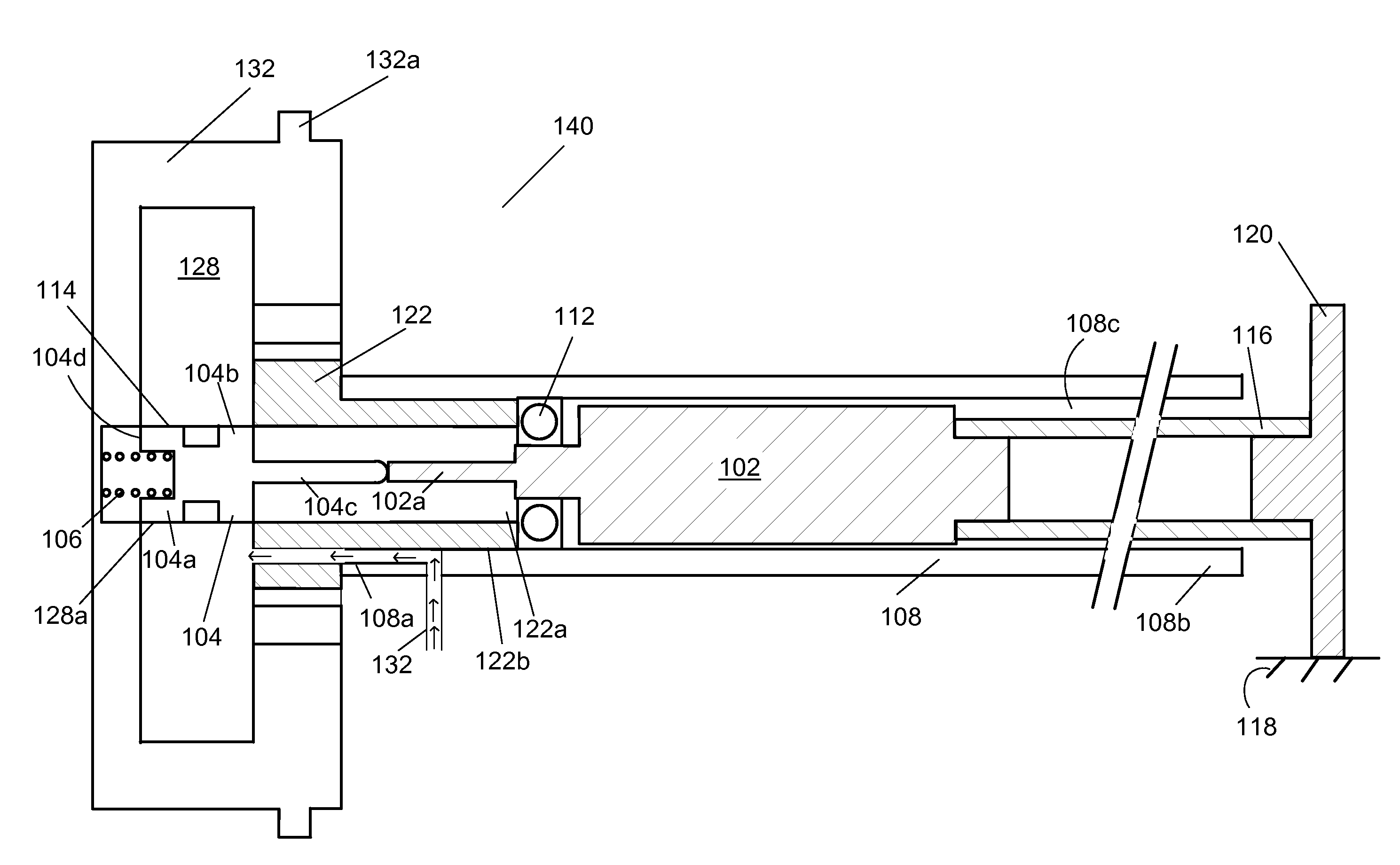
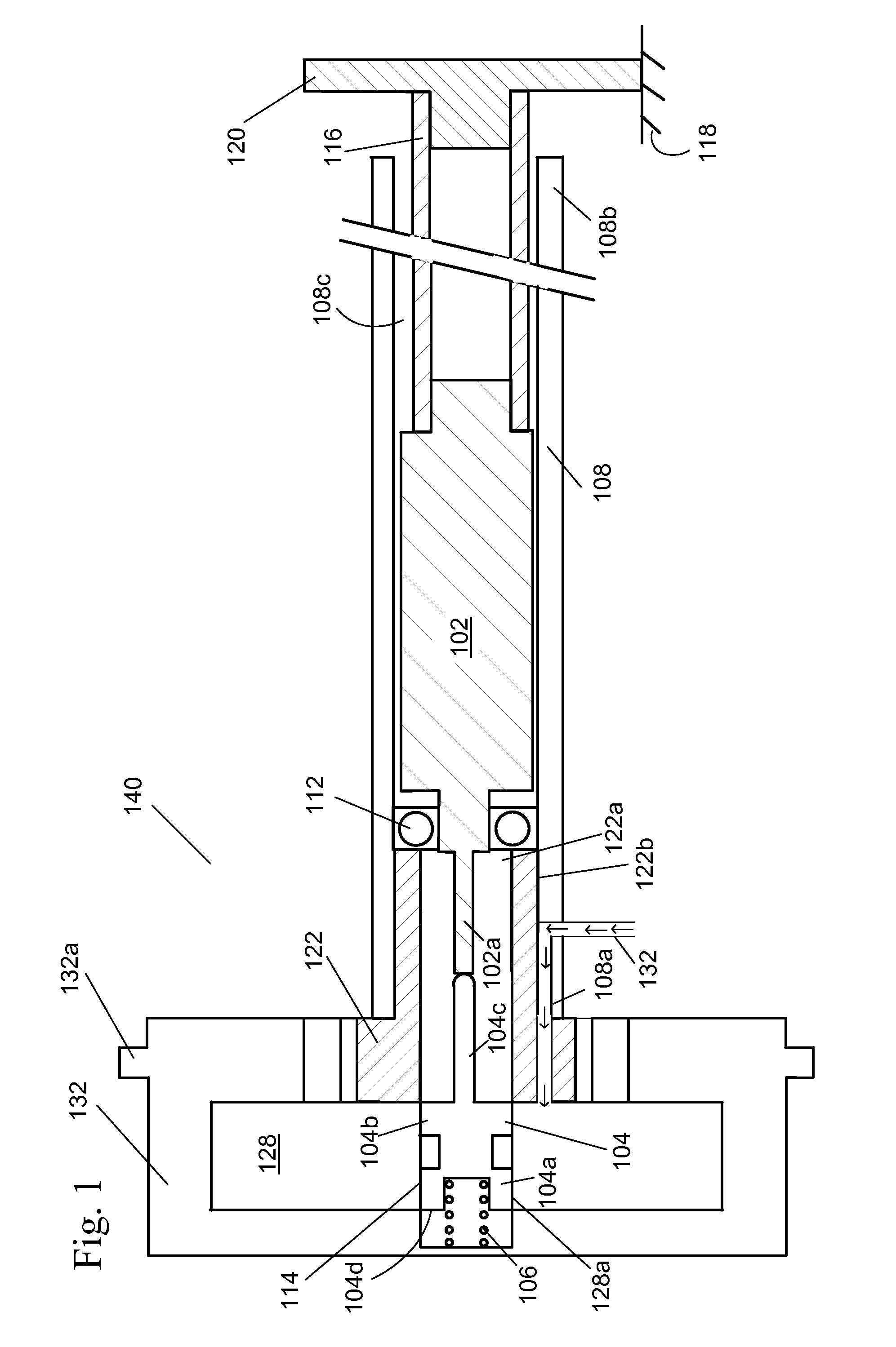
[0013]FIG. 1 shows a drawing of the timing controls for a variable cam timing mechanism mounted within the camshaft. The VCT mechanism may use one or more “vane phasers” on the engine camshaft (or camshafts, in a multiple-camshaft engine). In most cases, the phaser has a rotor 128 with one or more vanes, mounted to a first end 108a of the camshaft 108, and surrounded by a housing 132 forming a chamber between the rotor and the housing in which the vanes (not shown) fit. The housing 132 of the VCT mechanism 140 includes teeth 132a for accepting drive force through a chain, usually from the crankshaft (not shown), or possibly from another camshaft in a multiple-cam engine. The flange 122 received by the housing 132 is mounted on the camshaft 108.

[0014]A control valve 114 is present in the rotor 128. The position of the control valve 114 is altered by the control valve actuator or variable force solenoid 102. The control valve 114 controls the flow of fluid to the vanes, which move and...


PUM


Abstract

An internal combustion engine in which the variable cam timing controls for a variable cam timing mechanism include a variable force solenoid mounted within a hollow portion of the camshaft. The variable force solenoid is maintained in place within the hollow camshaft by a tubular shaft fixed to the engine and a bearing between the solenoid and the variable cam timing mechanism.

Description

REFERENCE TO RELATED APPLICATIONS[0001]This application claims an invention which was disclosed in Provisional Application No. 60 / 948,219, filed Jul. 6, 2007 entitled “VARIABLE CAM TIMING CONTROLS MOUNTED IN THE CAMSHAFT”. The benefit under 35 USC §119(e) of the United States provisional application is hereby claimed, and the aforementioned application is hereby incorporated herein by reference.BACKGROUND OF THE INVENTION[0002]1. Field of The Invention[0003]The invention pertains to the field of variable cam timing. More particularly, the invention pertains to variable cam timing (VCT) controls mounted in the camshaft.[0004]2. Description Of Related Art[0005]In the prior art, variable cam timing controls are either mounted separately from the camshaft, phaser, or spool valve, and / or are present in the front cover of the internal combustion engine. Positioning of the variable cam timing controls separate from the housing increases the length of the valvetrain and thus increases the e...

Claims


Application Information

Patent Timeline
Patent Type & Authority Applications(United States)
IPC IPC(8): F01L1/34
CPCF01L1/047F01L1/3442F01L2001/34433F01L2001/34426F01L2001/0475
Inventor SIMPSON, ROGER T.BUTTERFIELD, ROGER P.SMITH, FRANKLIN R.
Owner BORGWARNER INC
Why Eureka
Try Eureka