

Method For Feeding Staples In a Low Profile Surgical Stapler
- Summary
- Abstract
- Description
- Claims
- Application Information
AI Technical Summary
Problems solved by technology
Method used
Image

Examples
Embodiment Construction
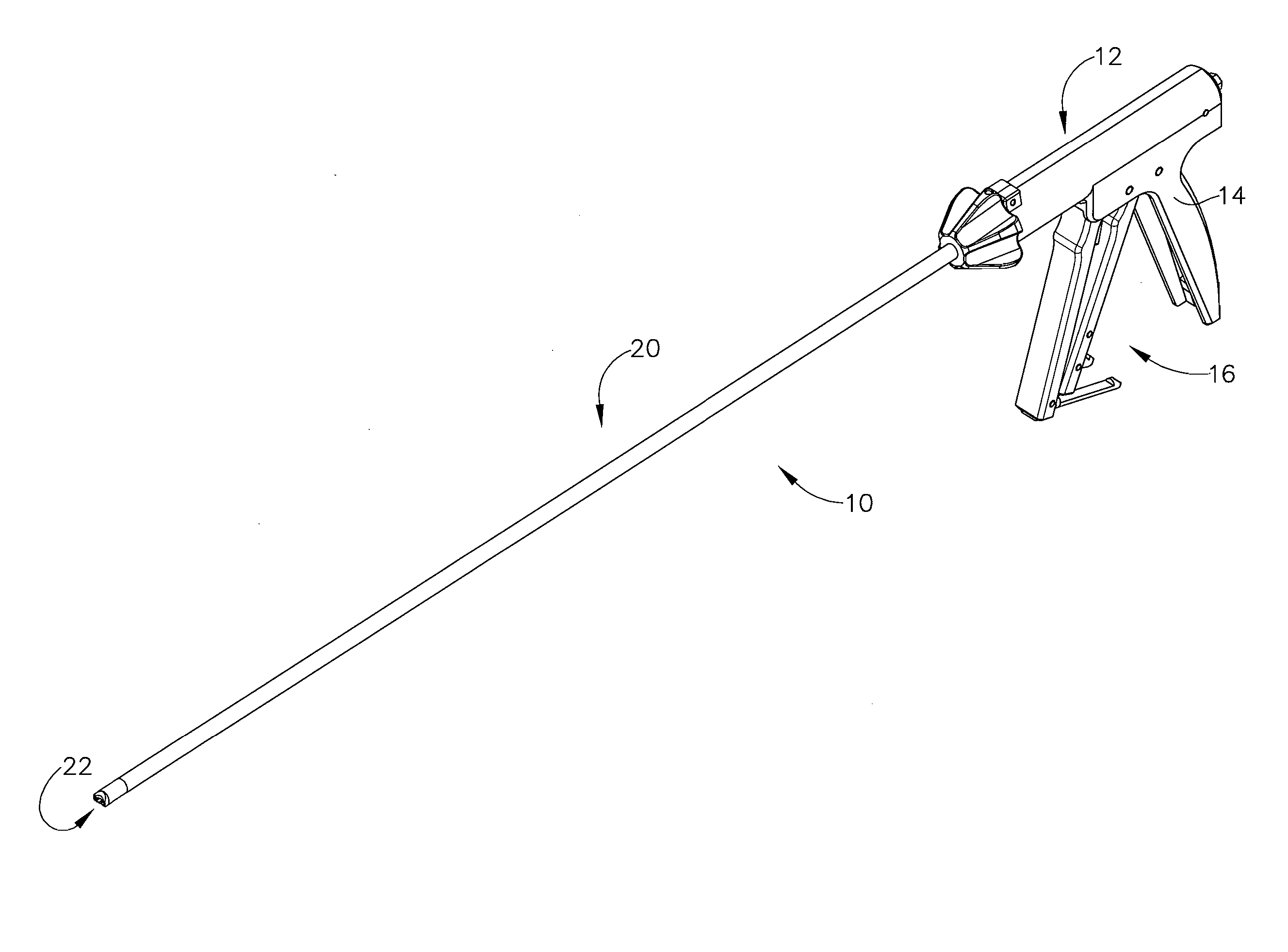
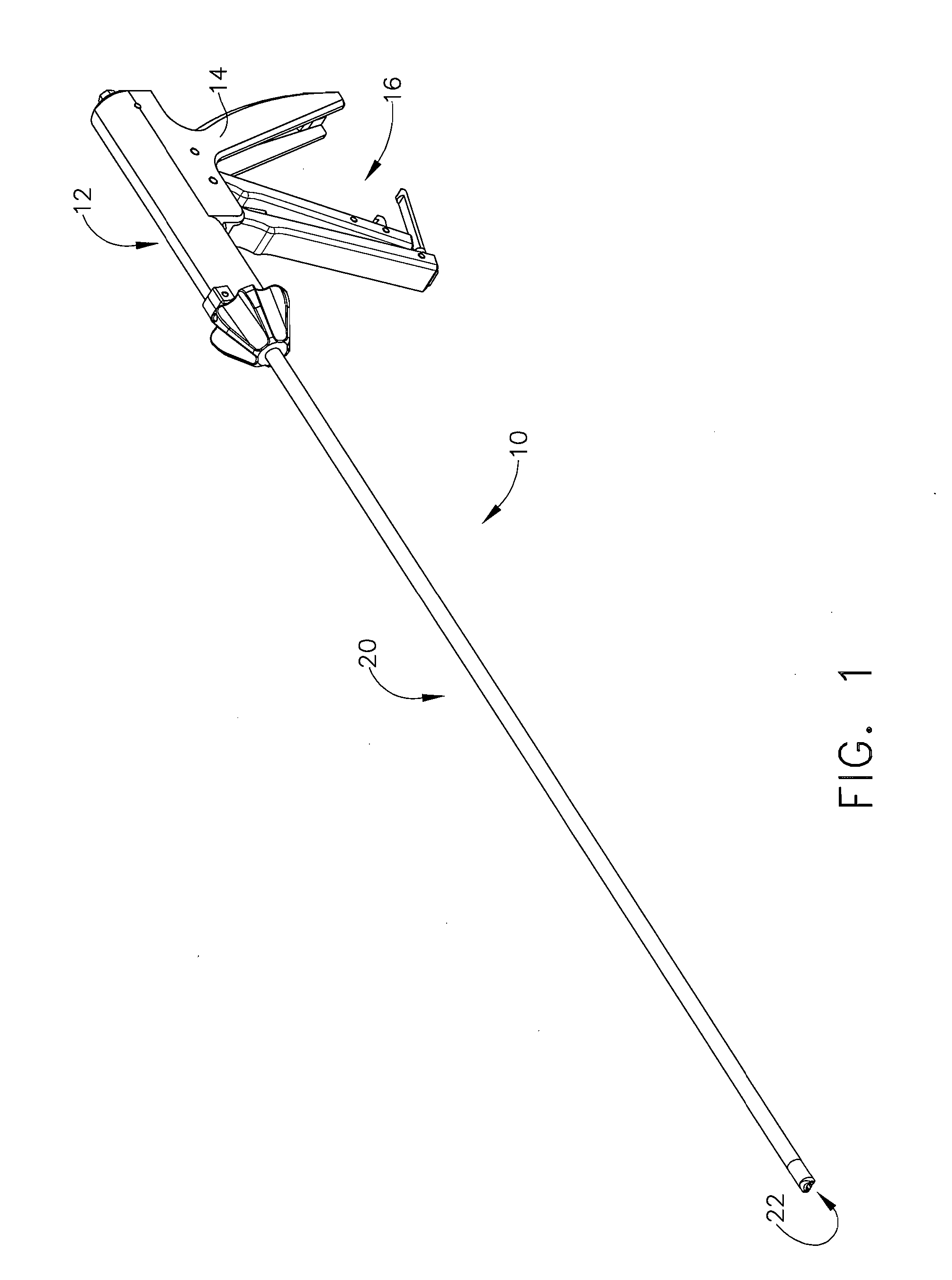
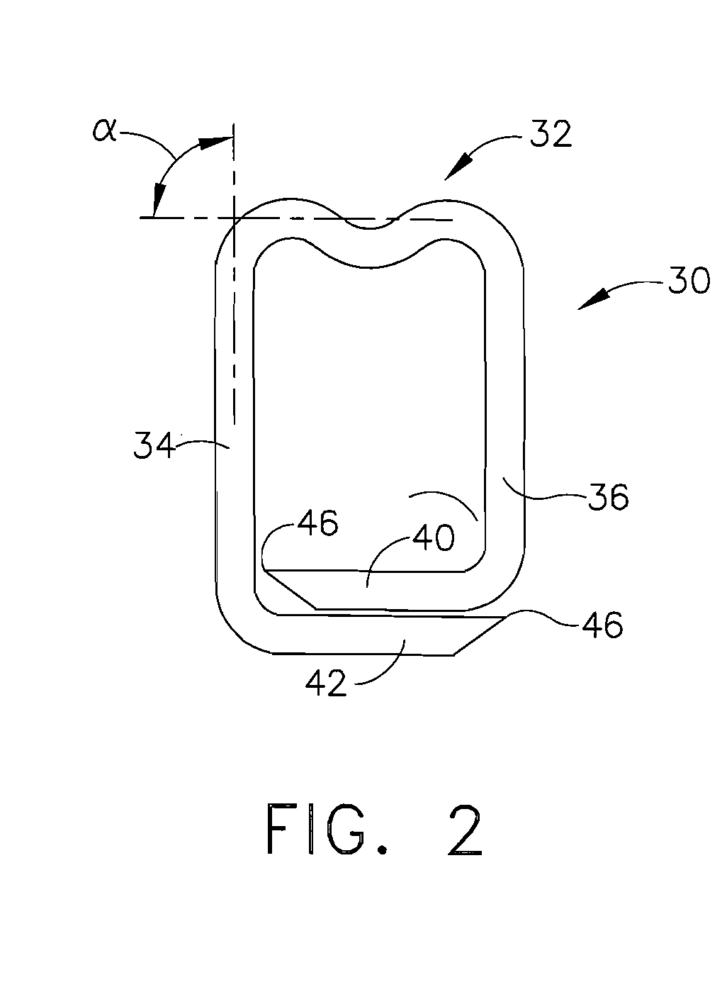
[0050]Referring again to the drawing figures, in which like numerals indicate like elements throughout the views, FIG. 3 shows the distal end of stapler 10 incorporating a first exemplary staple feeding mechanism of the present invention. As shown in FIG. 3, stapler 10 includes a staple former 50 which is attached to the distal end of staple housing 20. Staple deployment opening 22 is located at the distal end of former 50. Former 50 includes an inner channel (not shown) for conveying staples through the former and outside the stapler during deployment. Following passage of a staple outside opening 22, and the opening of the staple, former 50 advances over the opened staple to shape and close the staple through one or more tissue layers. Staples 30 are individually conveyed through former 50 and opening 22 by an anvil 52. Anvil 52 includes a pair of upwardly curved, staple holding tine 56 which hold onto the staple during passage through the former. The proximal end of anvil 52 is s...
PUM
| Property | Measurement | Unit |
|---|---|---|
| Length | aaaaa | aaaaa |
| Color | aaaaa | aaaaa |
| Shape | aaaaa | aaaaa |
Abstract
Description
Claims
Application Information