Depth control device for an underwater cable

a control device and cable technology, applied in underwater equipment, underwater construction, instruments, etc., can solve the problems of increasing drag, vibration, hydrodynamic noise, and increasing power required, and introducing errors into acoustic measurements

Inactive Publication Date: 2000-01-18
DIGICOURSE
View PDF12 Cites 89 Cited by
  • Summary
  • Abstract
  • Description
  • Claims
  • Application Information

AI Technical Summary

Problems solved by technology

This arrangement is not ideal because disposing the motor output shaft and the pitch axes in different planes increases the height of the depth control device, resulting in increased drag, vibrations, and hydrodynamic noise.
The...

Method used


Image

  • Depth control device for an underwater cable
  • Depth control device for an underwater cable
  • Depth control device for an underwater cable

Examples


Embodiment Construction

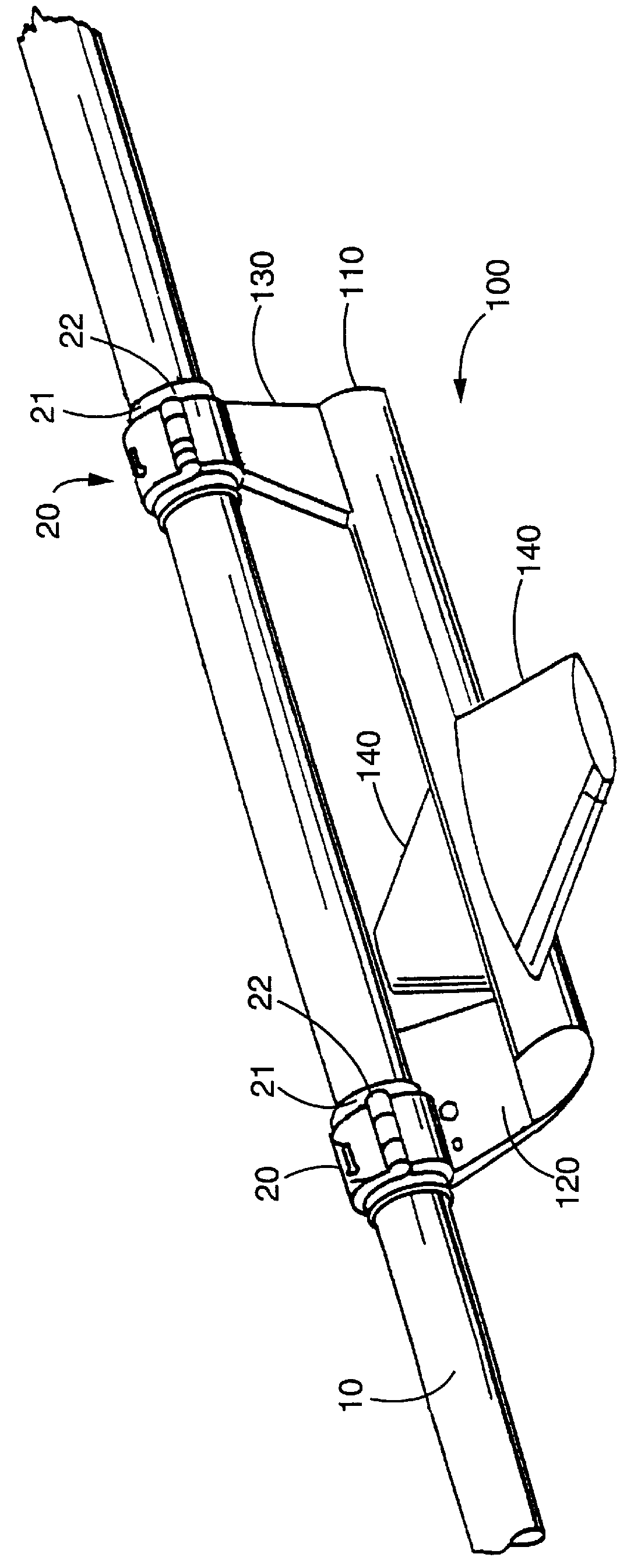
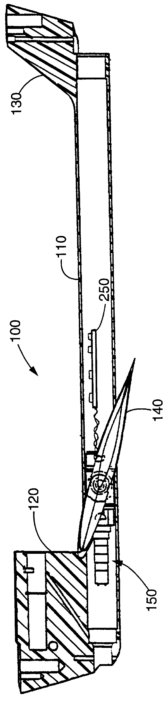
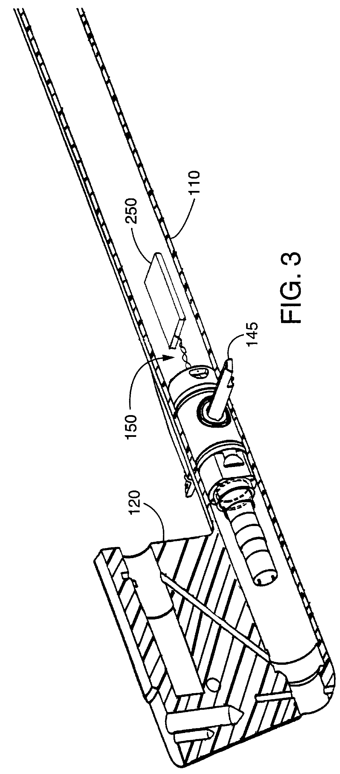
FIG. 1 illustrates an embodiment of a depth control device 100 according to the present invention installed on an underwater cable 10 for seismic exploration. During use, the cable 10 is towed through the water to the left in the figure by an unillustrated vessel. The depth control device 100 can be mounted on the cable 10 in any manner which enables the depth control device 100 to exert an upwards or downwards force on the cable 10 to adjust the depth of the cable 10 in the water. In the present embodiment, the depth control device 100 is suspended beneath the cable 10, but it may be disposed in other locations, such as above the cable 10, on the sides of the cable 10, or coaxially in-line with or surrounding the cable 10. A variety of other unillustrated components may be attached to the cable 10, such as heading sensors, hydrophones, acoustic ranging devices, cable retrieval devices, buoyancy adjusting equipment, and side scan sonar equipment. The depth control device 100 include...


PUM


Abstract

A depth control device for an underwater cable includes a rotary actuator having a rotating output shaft connected to a swash plate. Rotation of the swash plate by the actuator causes a rocker arm to pivot about an axis transverse to the axis of the output shaft. The rocker arm is drivingly connected to a drive shaft for rotating wings about their pitch axes. The pitch axes of the wings can be perpendicular to and intersecting the axis of the actuator output shaft, enabling the depth control device to be extremely compact.

Description

1. Field of the InventionThis invention relates to a depth control device for use with an underwater cable, such as one used in seismic testing.2. Description of the Related ArtIn marine seismic exploration, a cable, commonly referred to as a streamer cable, is towed underwater by a surface vessel. An array of hydrophones is mounted in or attached to the cable, and an acoustic source or gun is fired to force an impulse of compressed air into the water, creating a bubble. The collapse of the bubble generates acoustic pulses that radiate through the water and into the earth. Reflections of the pulses off geologic structures beneath the sea floor are picked up by the hydrophones, and data representing the detected reflections are transmitted to the surface vessel. By analyzing the reflections, it is possible to discover subsea formations of oil or gas.It is desirable to accurately control the, depth of the cable as it is being towed through the water. For this purpose, depth control de...

Claims


Application Information

Patent Timeline
IPC IPC(8): B63B21/56B63B21/66G01V1/38
CPCB63B21/66G01V1/3826
Inventor OLIVIER, ANDREW.RAGAN, BRYANT G.CRONVICH, JAMES T.
Owner DIGICOURSE
Why Eureka
Try Eureka