
Deflectable sheath handle assembly and method therefor

a technology of deflectable sheath and handle, which is applied in the direction of catheters, medical devices, other medical devices, etc., can solve the problems of increased fatigue of pull wires, difficulty in accurately positioning catheters in certain body vessels, and awkward mechanisms or the use of two hands, so as to achieve a larger size sheath and facilitate the distal end positioning

Active Publication Date: 2009-11-10
WILSON GREATBATCH LTD
View PDF22 Cites 83 Cited by
  • Summary
  • Abstract
  • Description
  • Claims
  • Application Information

AI Technical Summary

Benefits of technology

[0010]What is needed is a deflectable catheter that overcomes the shortcomings of previous deflectable catheters. What is further needed is a deflectable catheter that allows for more ease positioning of the distal end of the deflectable catheter, for example for a catheter having a relatively larger sized sheath, and that is usable with a single hand.

Problems solved by technology

However, with conventional catheter steering mechanisms, it can be difficult to accurately position the catheters in certain body vessels, such as branch veins.
For instance, the mechanisms are awkward or require the use of two hands.
Other steering mechanisms require pull wires to be wound and unwound around a rotatable cam wheel, causing increased fatigue on the pull wires, and potentially shortening the life of the device.
Furthermore, some deflectable catheters involve relatively large catheter sheaths.
The larger sheaths can be difficult to manipulate within a patient, and have increased deflection forces, frustrating efforts of a physician attempting to control deflection angle during a procedure.

Method used


Image

  • Deflectable sheath handle assembly and method therefor
  • Deflectable sheath handle assembly and method therefor
  • Deflectable sheath handle assembly and method therefor

Examples


Embodiment Construction

[0022]In the following detailed description, reference is made to the accompanying drawings, which form a part hereof, and in which is shown by way of illustration specific embodiments in which the invention may be practiced. These embodiments are described in sufficient detail to enable those skilled in the art to practice the invention, and it is to be understood that other embodiments may be utilized and that structural changes may be made without departing from the spirit and scope of the present invention. Therefore, the following detailed description is not to be taken in a limiting sense, and the scope is defined by the appended claims.

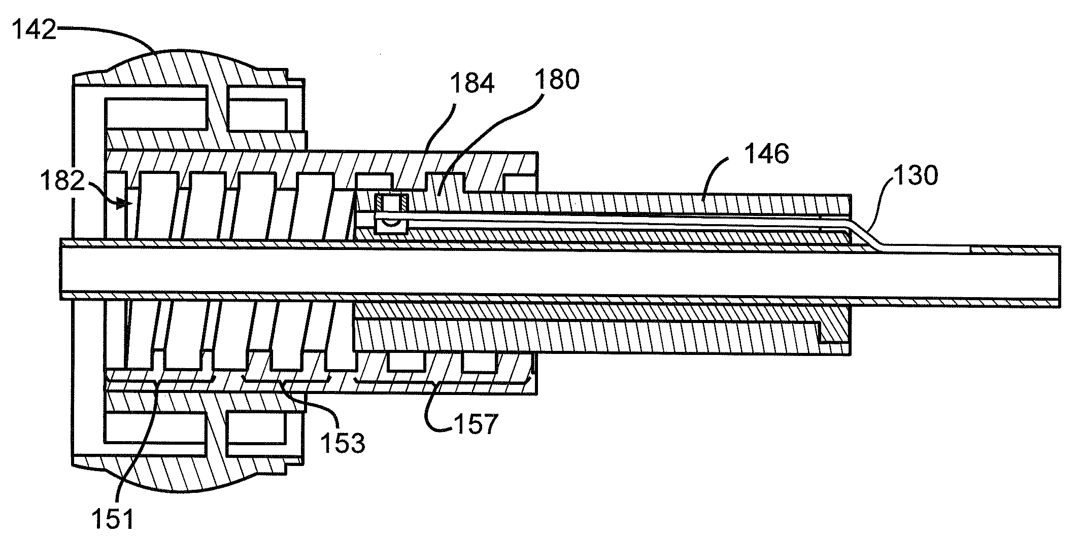
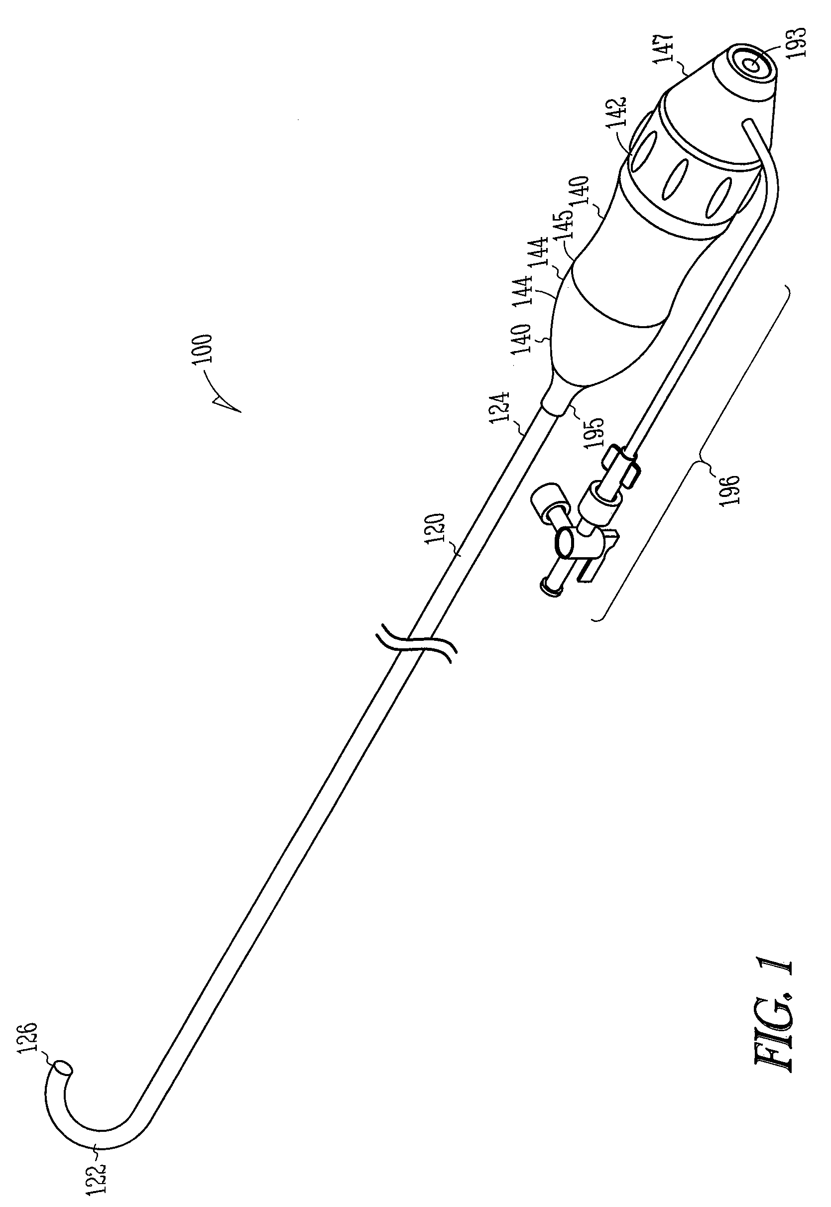
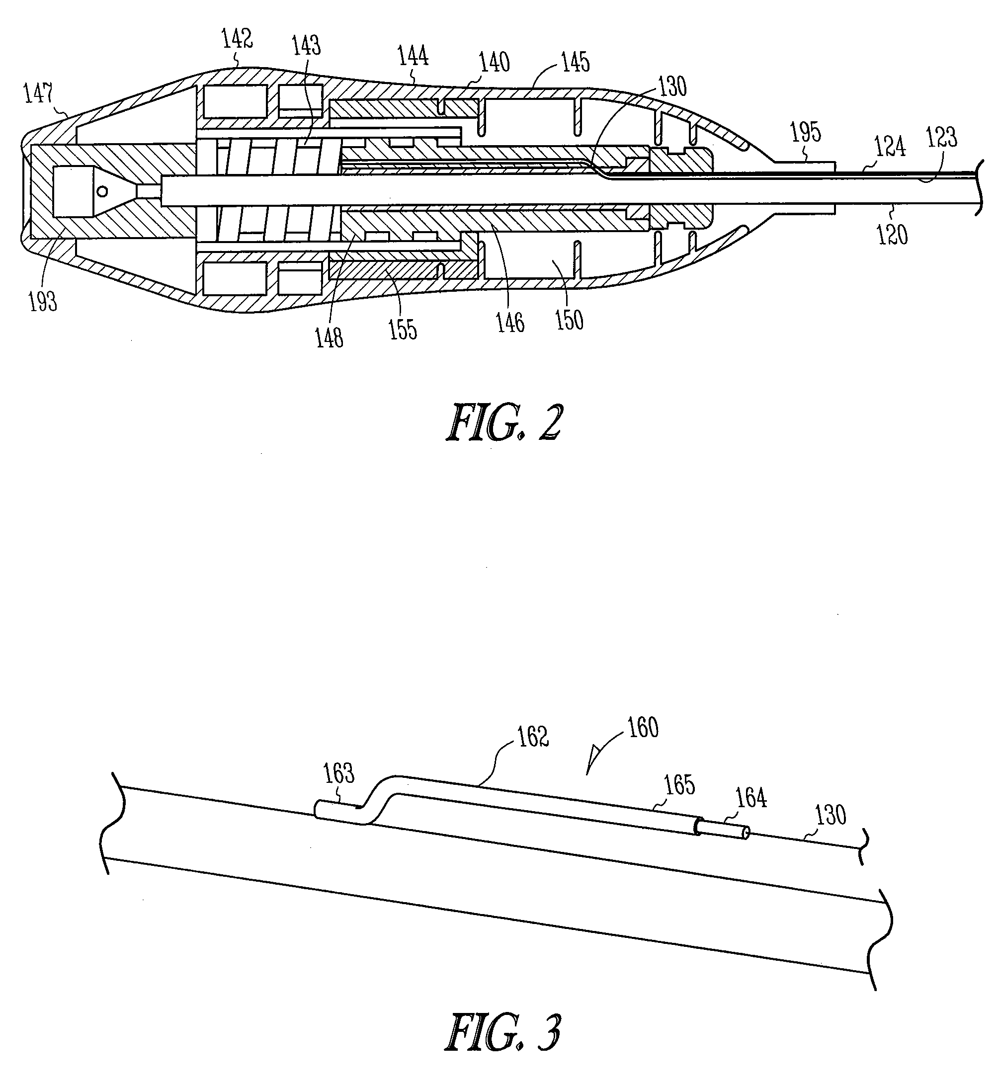
[0023]A deflectable sheath assembly 100 is illustrated in FIGS. 1 and 2, and generally includes a deflectable body 120, a handle assembly 140, and a pullwire 130. The deflectable body 120 extends from a distal end portion 122 to a proximal end portion 124, and includes a passage 123 therethrough. The passage 123 allows for instruments to be int...


PUM


Abstract

A deflectable catheter assembly includes a deflectable body manipulatable by a rotating actuator of a housing assembly. The housing assembly includes a sliding member having a threaded portion including a first threaded portion having a first pitch and a second threaded portion having a second pitch, where the first pitch is different than the second pitch.

Description

TECHNICAL FIELD[0001]Deflectable sheath assemblies having deflectable distal ends, and more particularly, a handle assembly for a deflectable sheath assembly.TECHNICAL BACKGROUND[0002]Medical devices and / or procedures are used in many different branch vessels and require a wide variety in placement techniques. One example of a placement technique is through use of a deflectable sheath. Typically, a deflectable sheath is controlled at a proximal end of the catheter by a control handle that operates a pull wire to deflect the sheath. However, with conventional catheter steering mechanisms, it can be difficult to accurately position the catheters in certain body vessels, such as branch veins. For instance, the mechanisms are awkward or require the use of two hands. Other steering mechanisms require pull wires to be wound and unwound around a rotatable cam wheel, causing increased fatigue on the pull wires, and potentially shortening the life of the device. Furthermore, some deflectable...

Claims


Application Information

Patent Timeline
Patent Type & Authority Patents(United States)
IPC IPC(8): A61M25/00
CPCA61M25/0136
Inventor SCHEIBE, GRANT ALEXANDERFISCHER, BRIANKNIPPEL, BRADLEY CHARLESPOPOWSKI, JEFFREY A.
Owner WILSON GREATBATCH LTD
Learn More