Radiation imaging apparatus

a technology of radiation imaging apparatus and connector, which is applied in the direction of image-conversion/image-amplification tubes, instruments, tubes with screens, etc., can solve the problems of troublesome tasks, possible unmation of the connector from the connection terminal, and impeded access to the connection terminal, so as to achieve convenient connection

Active Publication Date: 2013-04-04
FUJIFILM CORP
View PDF21 Cites 22 Cited by
  • Summary
  • Abstract
  • Description
  • Claims
  • Application Information

AI Technical Summary

Benefits of technology

[0027]According to the present invention, the positional relation including the distance and the direction of the connection terminal with respect to the center line of the electronic cassette is the same as that of the connector with respect to the center line of the imaging stand. Therefore, even if the electronic cassette of any size is mounted on the imaging stand, the electronic cassette is properly positioned in the imaging stand with ease. Moreover, the electronic cassette is easily connected through a cable to the external device disposed outside the imaging stand.

Problems solved by technology

Thus, when trying to connect the communication cable to the connection terminal of the electronic cassette mounted on the imaging stand, the imaging stand possibly hinders access to the connection terminal, though it depends on the position of the connection terminal, and prevents the connection of the communication cable.
However, when trying to mount the electronic cassette with the communication cable on the imaging stand, the communication cable sometimes interferes with the mounting and needs routing, and brings about a troublesome task.
Furthermore, since a magnet the fixed power of which is not so strong is generally used for fixing the connector of the communication cable to the connection terminal of the electronic cassette due to its ease of mating and unmating, the connector is possibly unmated from the connection terminal during the mounting or during moving the imaging stand with the electronic cassette.
If radiography is performed without notice of the unmating of the connector from the connection terminal, the AEC function does not work appropriately, so the patient receives an excessive X-ray dose.
On the other hand, if the connector is firmly locked in the connection terminal using claws, when the communication cable gets snagged in moving the imaging stand, the connection terminal and the connector easily break.
However, the holder of the US Patent Application Publication No. 2011 / 0110497 is compliant with only a single size of electronic cassette, so another size of electronic cassette cannot be mounted thereon.
However, this imaging table is designed for a conventional film cassette and IP cassette, and hence is not intended to have a connector for connection to the electronic cassette.

Method used


Image

  • Radiation imaging apparatus
  • Radiation imaging apparatus
  • Radiation imaging apparatus

Examples


first embodiment

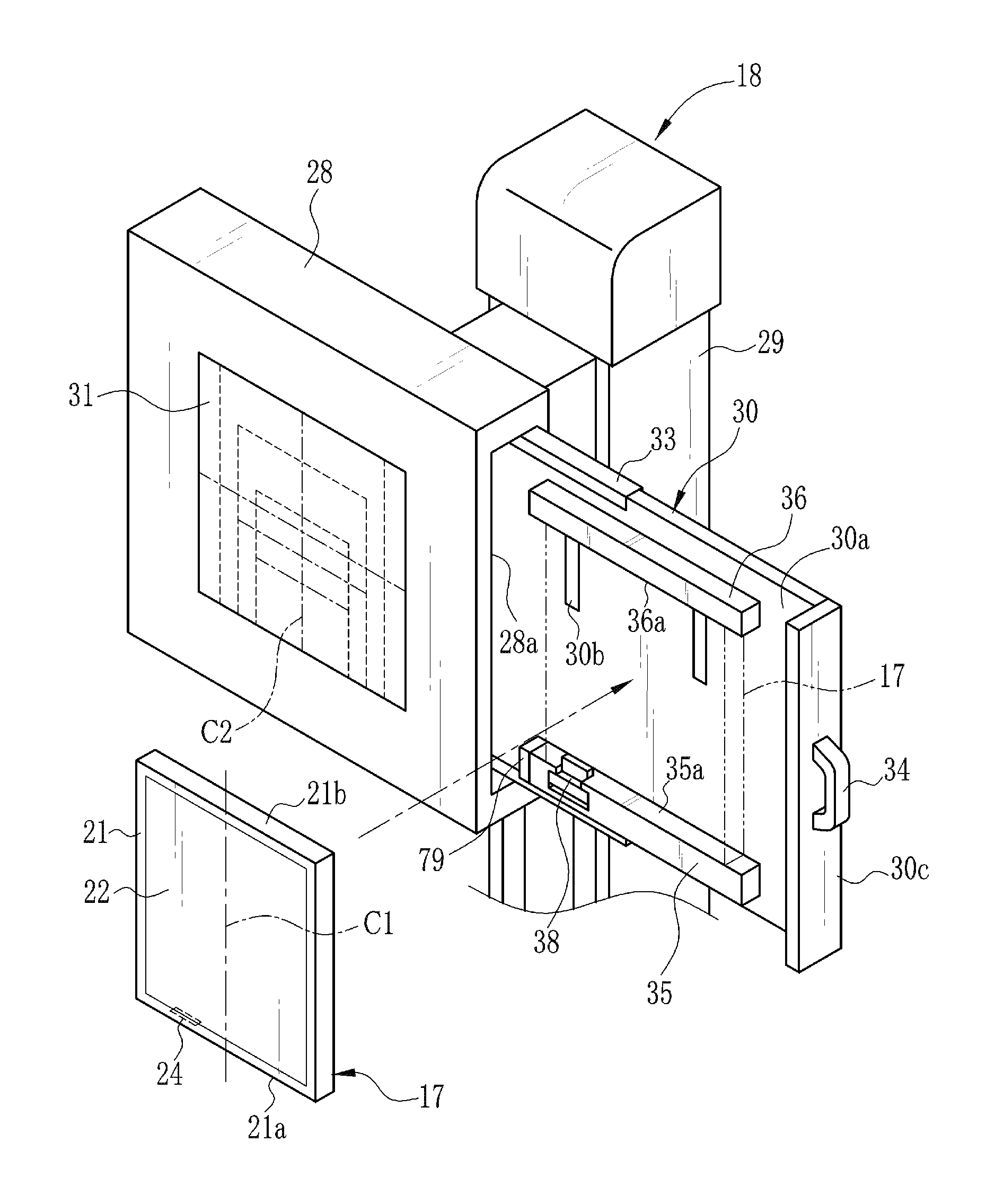
[0095]The first relay terminal 79 is provided in the first catch member 35, as with the external connection terminal 43 (see FIGS. 4 and 5) of the However, in contrast to the external connection terminal 43, the first relay terminal 79 is provided on a surface of the first catch member 35 opposite to the surface of the external connection terminal 43, in other words, the side surface on the opposite side of the tray insertion slot 28a in a state where the tray 30 is loaded into the cassette holder 28. The second relay terminal 80 is disposed inside the cassette holder 28. The second relay terminal 80 to be directly connected to the first relay terminal 79 is positioned in the depths of the tray insertion slot 28a so as to face the first relay terminal 79. The second relay terminal 80 is connected to the first relay terminal 79 when the tray 30 is loaded into the cassette holder 28. The second relay terminal 80 is disconnected from the first relay terminal 79 when the tray 30 is unl...

second embodiment

[0096]The relay cable 81 routed through the column 29 and the cassette holder 28 mediates between the external connection terminal 82 and the second relay terminal 80. To the external connection terminal 82, a multi connector 84 of a multi cable 83 is connected. In the second embodiment, the electronic cassette 17 is connected to the multi cable 83 extending from the console 13 through the multi connector 38, the first relay terminal 79, the second relay terminal 80, the relay cable 81, and the external connection terminal 82. Note that, the above structure of the relay terminal and the relay cable for relaying between the external connection terminal 82 and the multi connector 38 is just an example, and the number of the relay terminals and the relay cables is appropriately changeable.

[0097]The second embodiment, in contrast to the first embodiment, can eliminate the need for mating the multi cable 45 to the external connection terminal 43 inside the tray 30, so preparation for rad...


PUM


Abstract

A cassette holder of an imaging stand is provided with first and second catch members for catching and holding an electronic cassette from above and below. The first catch member has a multi connector connected to a multi terminal of the electronic cassette. The multi connector is offset with respect to a center line of an imaging surface of the cassette holder. The multi terminal is offset with respect to a center line of an irradiation surface of the electronic cassette in the same direction by the same amount as those of the multi connector. In a state where said electronic cassette mounted on a tray is loaded into the cassette holder, the center line of the irradiation surface coincides with the center line of the imaging surface.

Description

BACKGROUND OF THE INVENTION[0001]1. Field of the Invention[0002]The present invention relates to a radiation imaging apparatus having an electronic cassette and an imaging stand that holds the electronic cassette.[0003]2. Description Related to the Prior Art[0004]In a medical field, a radiation image capturing system, for example, an X-ray image capturing system is constituted of an X-ray generating apparatus for generating X-rays and an X-ray imaging apparatus for taking an X-ray image by reception of the X-rays. The X-ray generating apparatus includes an X-ray source for emitting the X-rays to a patient's body, a source controller for controlling the operation of the X-ray source, and an exposure switch for inputting an emission start command of the X-rays. The X-ray imaging apparatus has an electronic cassette, which receives the X-rays having passed through the patient's body and produces the X-ray image.[0005]The electronic cassette is composed of a flat panel detector (FPD) an...

Claims


Application Information

Patent Timeline
Patent Type & Authority Applications(United States)
IPC IPC(8): H05G1/64H05G1/38
CPCA61B6/4283G01D18/00A61B6/56A61B6/542
Inventor TAJIMA, TAKASHIKITAGAWA, YUSUKE
Owner FUJIFILM CORP
Why Eureka
Try Eureka