Manufacturing method for liquid ejecting head unit, and liquid ejecting apparatus

a technology of liquid ejecting head unit and manufacturing method, which is applied in the direction of metal-working apparatus, printing, writing implements, etc., can solve the problems of increased components and higher costs, and achieve the effects of convenient positioning, favorable positioning accuracy and easy manufacturing of the head uni

Active Publication Date: 2010-11-18
SEIKO EPSON CORP
View PDF3 Cites 20 Cited by
  • Summary
  • Abstract
  • Description
  • Claims
  • Application Information

AI Technical Summary

Benefits of technology

[0009]An advantage of some aspects of the invention is to provide a manufacturing method for a liquid ejecting head unit capable of anchoring liquid ejecting heads to a base plate in accordance with a resolution while maintaining a favorable positioning accuracy and without increasing the number of components, and to provide a liquid ejecting apparatus that uses this liquid ejecting head unit.
[0010]A manufacturing method for a liquid ejecting head unit according to an aspect of the invention is a manufacturing method for a liquid ejecting head unit that includes: a plurality of liquid ejecting heads, each liquid ejecting head having a nozzle row in which nozzles that eject a liquid are arranged in a row; a base plate to which the plurality of liquid ejecting heads are anchored; an anchoring plate, anchored to the base plate, for positioning the liquid ejecting heads in predetermined positions relative to the base plate; and a reference mark formed in the anchoring plate and a positioning mark formed in the base plate for positioning the anchoring plate relative to the base plate. A plurality of the positioning marks are formed along the direction in which the nozzles are arranged in a row, and the manufacturing method includes: selecting the positioning mark in accordance with a predetermined resolution; anchoring the anchoring plate to the base plate so that the reference mark and the selected positioning mark are in the same relative positional relationship; and anchoring the liquid ejecting heads to the base plate using the anchoring plate. Forming multiple positioning marks and selecting the positioning marks in accordance with a predetermined resolution makes it possible to manufacture head units having different resolutions with ease; it is thus unnecessary to manufacture components based on the resolution, thus making it possible to achieve a reduction in costs.
[0012]Here, it is preferable for at least one of the shape and size of the positioning marks to differ in each of positioning marks. Forming the positioning marks in this manner makes it easy to recognize which positioning marks are selected, and thus makes it easier to manufacture the head unit.
[0013]Furthermore, it is preferable for a plurality of rows of the positioning marks to be formed in the anchoring plate along the direction that is orthogonal to the direction in which the nozzles are arranged in rows. Providing a plurality of rows in this manner makes it easy to carry out positioning relative to the reference marks.
[0014]Furthermore, it is preferable for a positioning pin to be provided in the anchoring plate, and a through-hole through which the positioning pin passes to be provided in each of the liquid ejecting heads; and for each of the liquid ejecting heads to be anchored to the base plate by passing the positioning pin through the through-hole. According to this aspect of the invention, the liquid ejecting head can be positioned with ease using the positioning pin, and anchored.
[0015]A liquid ejecting apparatus according to another aspect of the invention includes a liquid ejecting head unit manufactured through one of the manufacturing methods for a liquid ejecting head unit described above. Using the manufacturing method for a liquid ejecting head unit according to the invention makes it possible to anchor liquid ejection heads to a base plate in accordance with a resolution while maintaining a favorable positioning accuracy and without increasing the number of components, and thus the liquid ejecting apparatus has favorable liquid ejection properties.

Problems solved by technology

However, with the method disclosed in JP-B-2549762, in the case where higher resolutions are to be obtained by disposing the liquid ejecting heads so as to be shifted in the nozzle row direction, it is necessary to form the key grooves based on the desired resolution, which leads to an increase in the number of components.
There is thus a problem that this results in higher costs.
It should be noted that this problem is not limited to ink jet recording heads, and is also present in other liquid ejecting head units that eject liquids aside from ink.

Method used


Image

  • Manufacturing method for liquid ejecting head unit, and liquid ejecting apparatus
  • Manufacturing method for liquid ejecting head unit, and liquid ejecting apparatus
  • Manufacturing method for liquid ejecting head unit, and liquid ejecting apparatus

Examples


Embodiment Construction

[0026]The invention will be described in detail hereinafter based on embodiments.

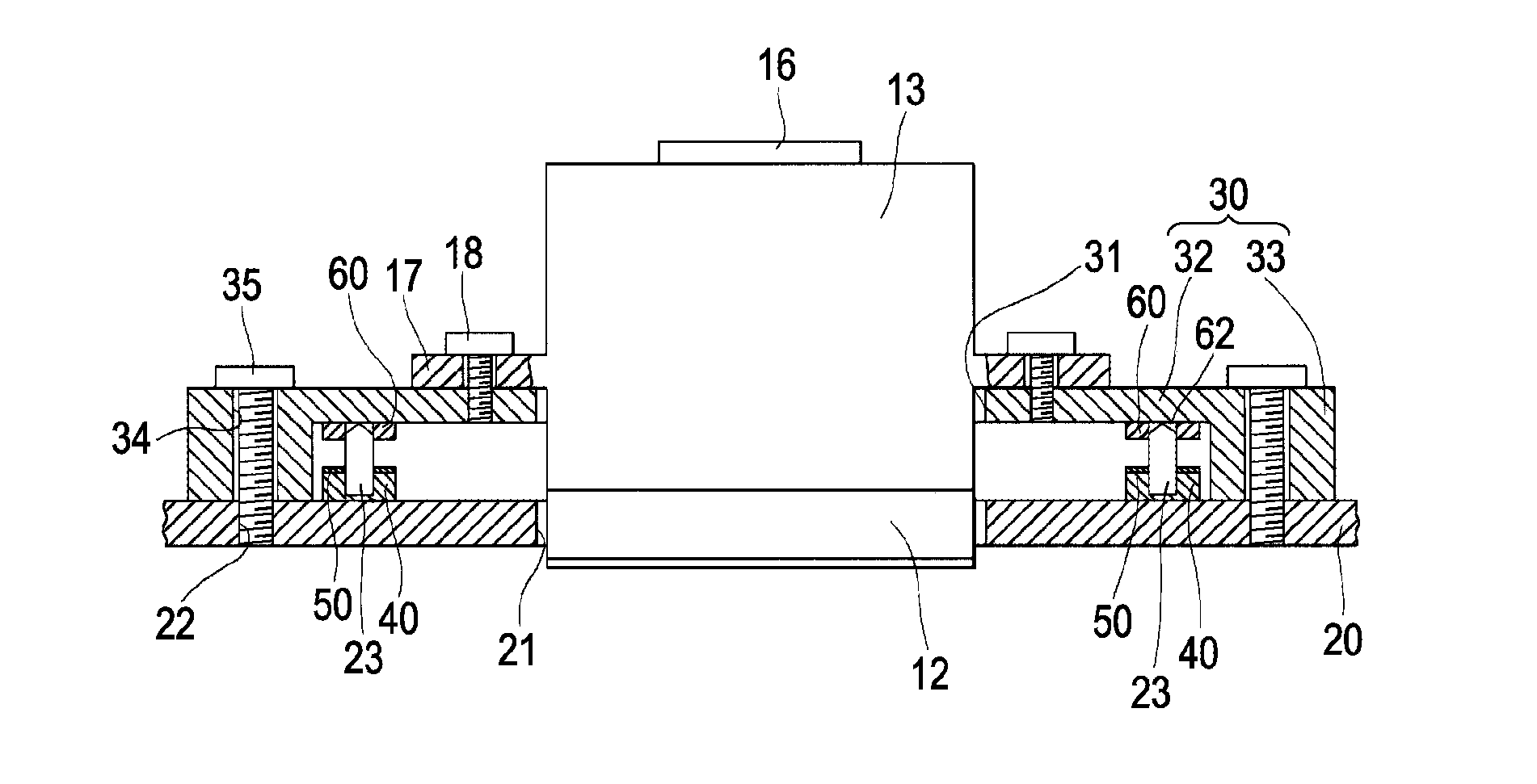
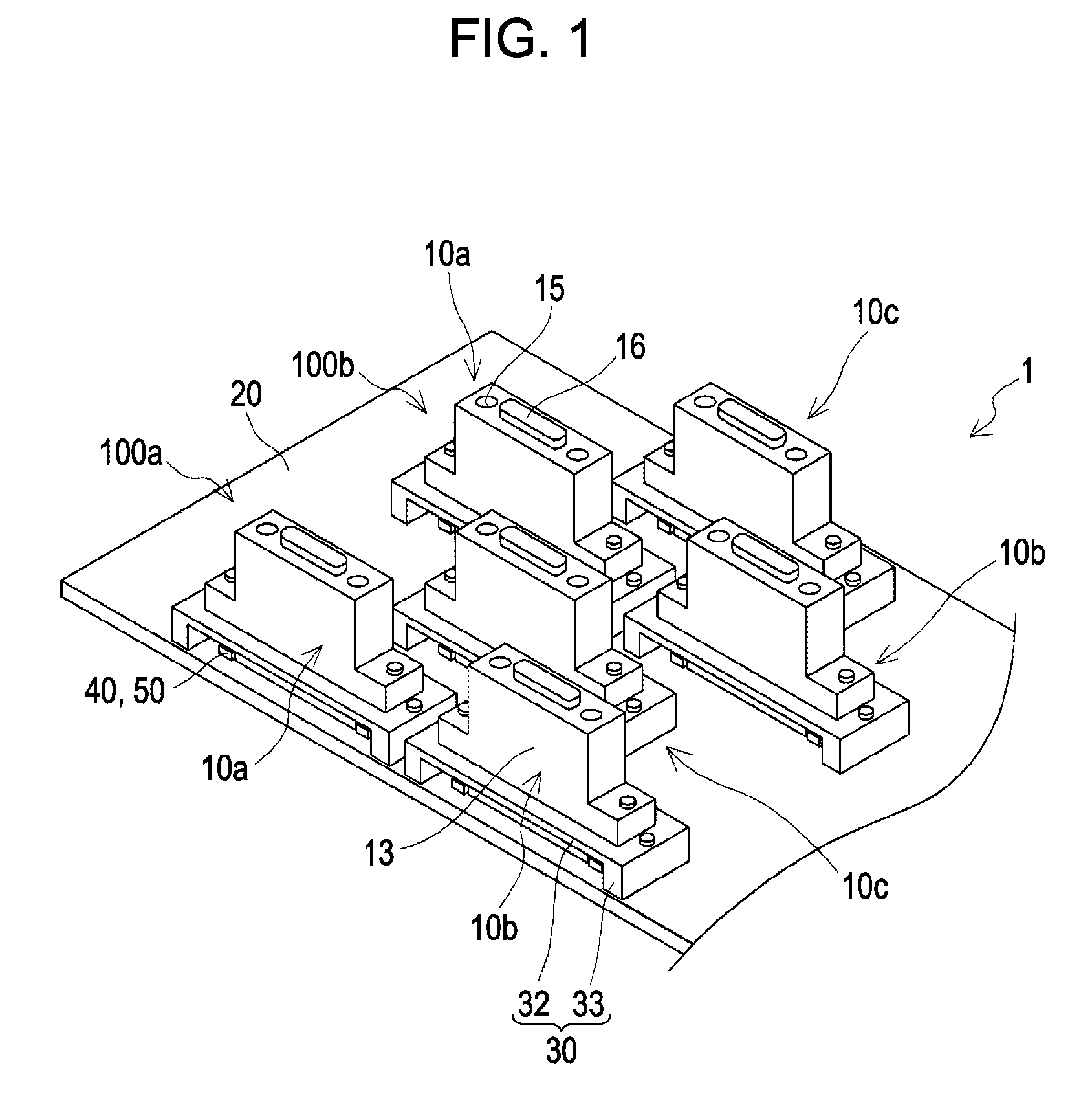
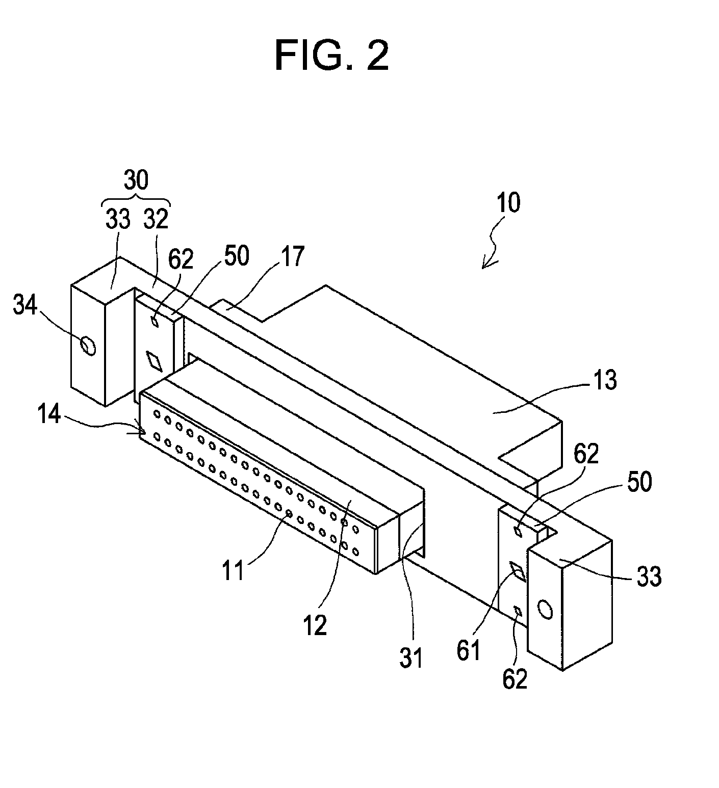
[0027]As shown in FIGS. 1 through 4, an ink jet recording head unit 1 according to this embodiment (also called simply a head unit hereinafter) includes head groups 100 configured of multiple ink jet recording heads 10 (also called simply heads hereinafter) and a base plate 20 onto which the multiple heads 10 are anchored having been positioned in predetermined positions.

[0028]Nozzles 11 are arranged at a constant pitch in one direction in each of the heads 10, thereby forming nozzle rows 14. Each head group 100 is configured by disposing multiple heads 10 (in this embodiment, heads 10a, 10b, and 10c as an example) so as to follow the direction of the nozzle rows 14. The multiple heads 10a, 10b, and 10c of which each head group 100 is configured are disposed in a houndstooth pattern. In other words, the heads 10a and the heads 10b are disposed in a row following the nozzle row direction, whereas the hea...


PUM

PropertyMeasurementUnit
shapeaaaaaaaaaa
sizeaaaaaaaaaa
liquidaaaaaaaaaa

Abstract

A liquid ejecting head unit includes liquid ejecting heads, each having a row of nozzles that eject liquid. The liquid ejecting heads are anchored to a base plate. An anchoring plate is anchored to the base plate and positions the liquid ejecting heads relative to the base plate. A reference mark is formed in the anchoring plate and a positioning mark is formed in the base plate for positioning the anchoring plate relative to the base plate. The positioning marks are formed along the direction in which the nozzles are arranged in a row. A related manufacturing method includes selecting the positioning mark in accordance with a predetermined resolution and anchoring the anchoring plate to the base plate so that the reference mark and the selected positioning mark are in the same relative positional relationship. The liquid ejecting heads are anchored to the base plate using the anchoring plate.

Description

BACKGROUND[0001]1. Technical Field[0002]The present invention relates to a manufacturing method for a liquid ejecting head unit and a liquid ejecting apparatus.[0003]2. Related Art[0004]Liquid ejecting apparatuses, as represented by ink jet recording apparatuses such as ink jet printers, plotters, and so on, include liquid ejecting head units in which multiple liquid ejecting heads capable of ejecting a liquid such as ink held in a cartridge, a tank, or the like as droplets from a nozzle are provided.[0005]Each of the multiple liquid ejecting heads of which such a liquid ejecting head unit is configured are anchored to a base plate, which is a shared holding member, in a state in which they are positioned in predetermined positions with high accuracy. For example, the liquid ejecting heads are anchored to the base plate along the direction of nozzle rows in which multiple nozzles of the liquid ejecting heads are arranged, and are positioned with high accuracy so that the nozzles are...

Claims


Application Information

Patent Timeline
Patent Type & Authority Applications(United States)
IPC IPC(8): B41J2/14B23P17/00
CPCB41J2/155Y10T29/49401B41J2202/20B41J2202/19
Inventor HAGIWARA, HIROYUKIWATANABE, SHUNSUKE
Owner SEIKO EPSON CORP
Why Eureka
Try Eureka