Battery assembly

a battery and assembly technology, applied in the field of battery assembly, can solve the problems of high cost and achieve the effect of increasing the number of components and cos

Active Publication Date: 2014-12-16
TOYOTA JIDOSHA KK
View PDF27 Cites 0 Cited by
  • Summary
  • Abstract
  • Description
  • Claims
  • Application Information

AI Technical Summary

Benefits of technology

[0006]The present invention was made in view of the problem described above, and its object is to provide a battery assembly whose inside can be cooled at a low cost, without increasing the number of components.
[0011]In the battery assembly in accordance with the present invention, the terminal portion, which is an essential component of the battery assembly, is also used as the cooling plate and, therefore, the battery assembly can well be cooled without increasing the number of components and cost.

Problems solved by technology

In the battery assembly mentioned above, however, a separate cooling tab is attached to each cooling plate and, therefore, the number of components increases, resulting in higher cost.

Method used


Image

  • Battery assembly
  • Battery assembly
  • Battery assembly

Examples


embodiment 1

[0025](Embodiment 1)

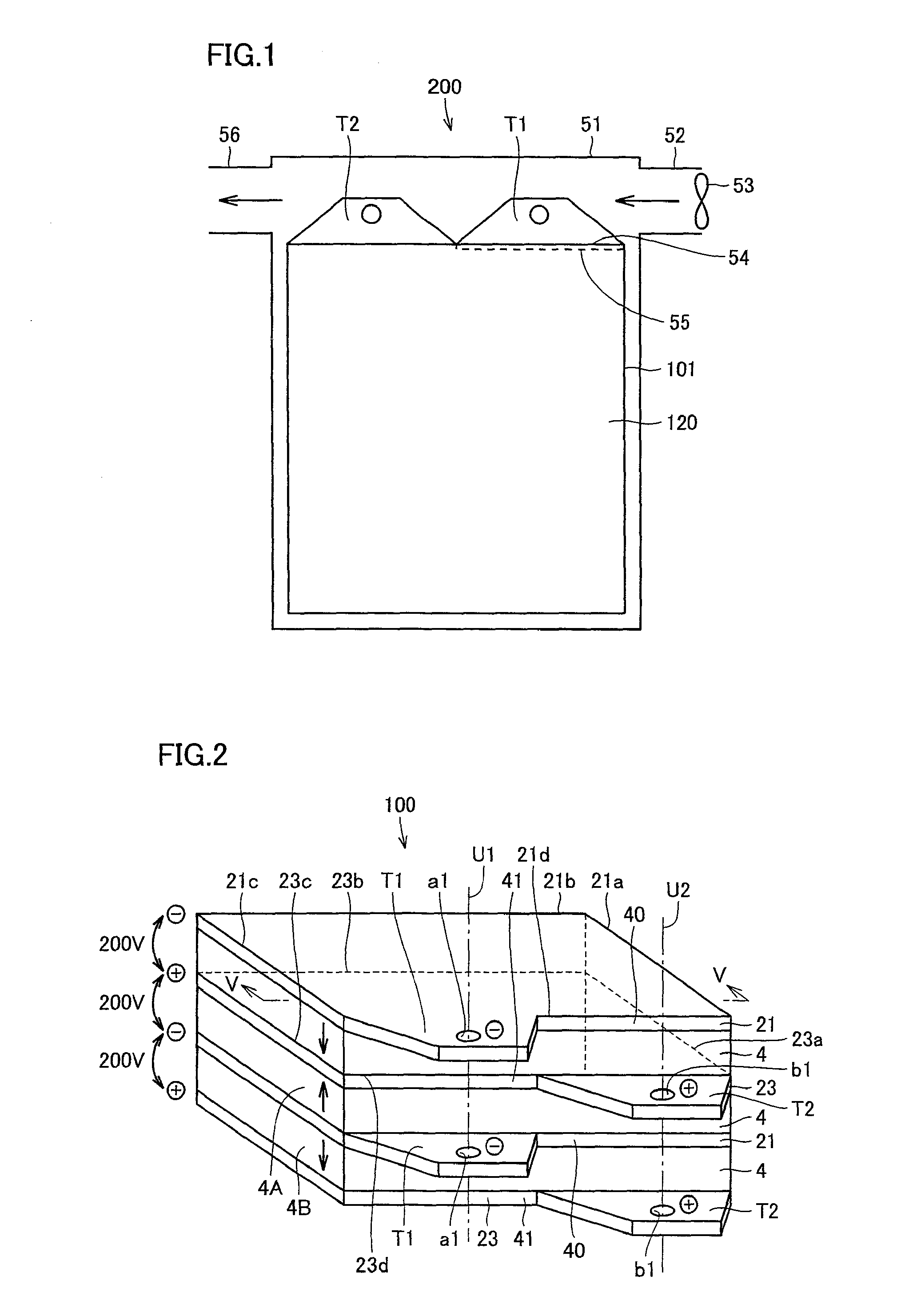
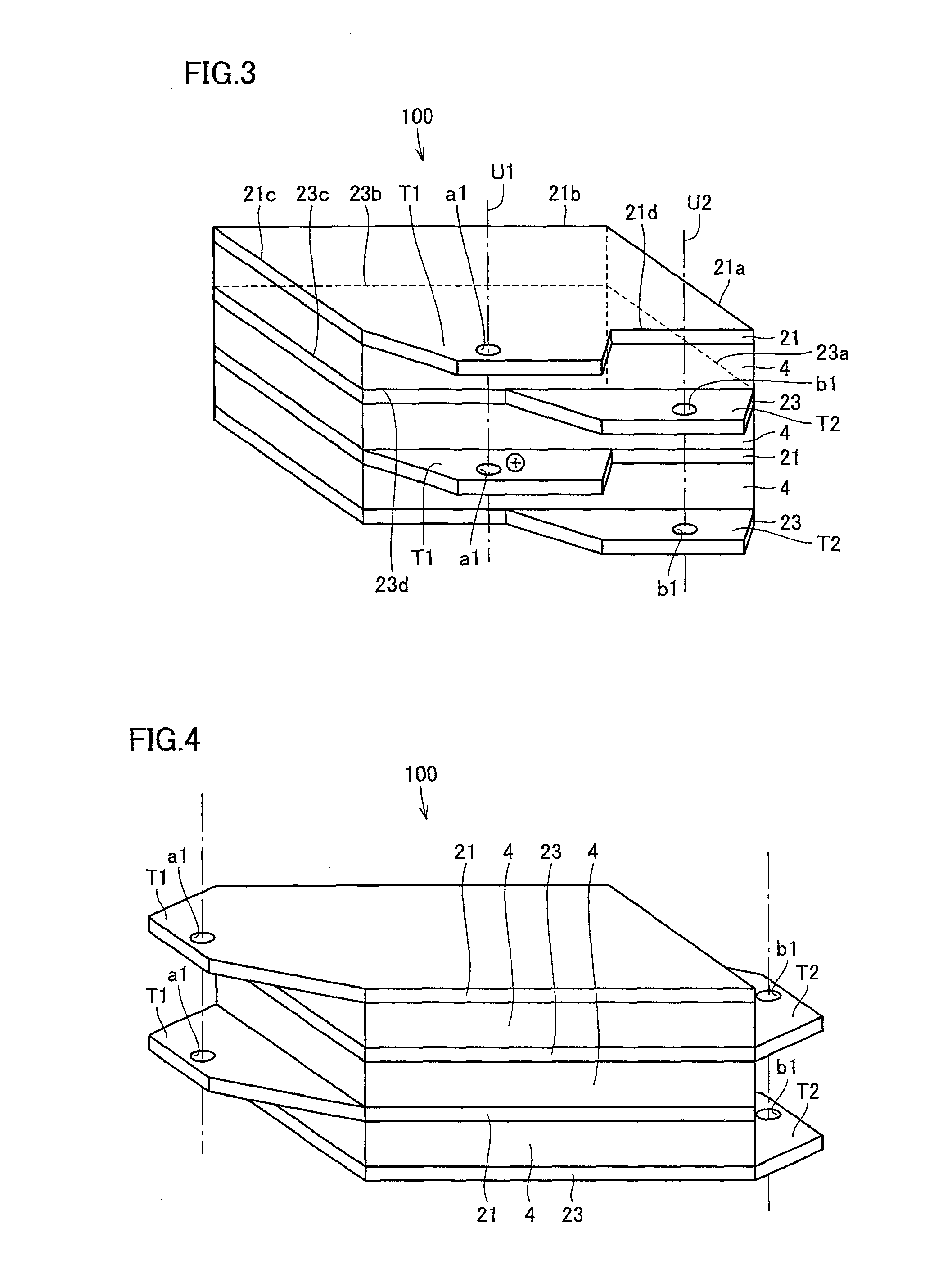
[0026]Referring to FIGS. 1 to 6, a battery assembly 100 in accordance with Embodiment 1 of the present invention will be described.

[0027]FIG. 1 is a plan view of a cooling apparatus 200 arranged around a battery pack 120 containing the battery assembly, for cooling a terminal portion of the battery assembly, and FIG. 2 is a perspective view of battery assembly 100 in accordance with Embodiment 1.

[0028]Cooling apparatus 200 of battery assembly 100 includes a housing 51 housing battery pack 120 therein, and a fan 53 for supplying outer air through an air intake duct 52 provided on housing 51.

[0029]Battery pack 120 is formed to have a substantially rectangular parallelepiped shape, and includes a casing 101 containing battery assembly 100 therein, and battery assembly 100. Battery pack 120 has a plurality of terminal portions T1 and T2 protruding outward from casing 101, on one side surface of battery pack 120. Fan 53 blows air (coolant) to terminal portions T1 and ...

embodiment 2

[0076](Embodiment 2)

[0077]Referring to FIGS. 7 to 13, a cooling apparatus for a battery assembly in accordance with Embodiment 2 of the present invention will be described. The same components as in the battery assembly 100 and its cooling apparatus 200 in accordance with Embodiment 1 above are denoted by the same reference characters, and description thereof will not be repeated.

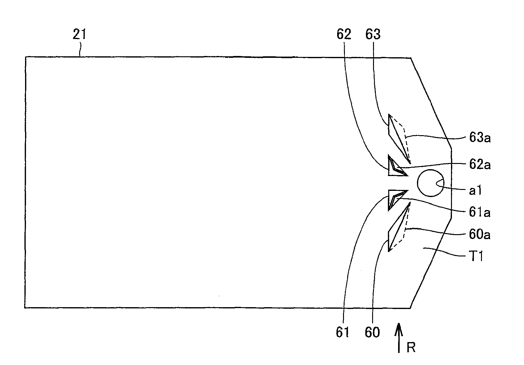
[0078]FIG. 7 is a plan view of negative collector electrode 21 provided at battery assembly 100 in accordance with Embodiment 2. As shown in FIG. 7, openings 60 to 63 are formed around connection hole a1 of terminal portion T1.

[0079]Around the openings 60 to 63, guide walls 60a to 63a are formed for guiding cooling air shown in FIG. 1 to openings 60 to 63.

[0080]Guide walls 60a to 63a are formed by cutting and folding parts of terminal portion T1, when openings 60 to 63 are formed. Therefore, guide walls 60a to 63a can be formed without increasing the number of components.

[0081]When air flows from the direct...


PUM

PropertyMeasurementUnit
conductiveaaaaaaaaaa
polarityaaaaaaaaaa
discharge poweraaaaaaaaaa

Abstract

A battery assembly of the invention includes a secondary battery formed by stacking a plurality of unit battery cells having a cathode and an anode, collector electrodes provided on respective end surfaces of the secondary battery positioned in the stacking direction of the unit battery cells; and terminal portions formed at the collector electrodes, protruded outward from a side surface of the secondary battery, to which conductive members are connected for charging and discharging. A coolant is supplied to the terminal portions to cool the terminal portions.

Description

[0001]This is a 371 national phase application of PCT / JP2007 / 062474 filed 14 Jun. 2007, claiming priority to Japanese Patent Application No. 2006-196980 filed 19 Jul. 2006, the contents of which are incorporated herein by reference.FIELD OF THE INVENTION[0002]The present invention relates to a battery assembly formed by stacking a plurality of secondary batteries.BACKGROUND OF THE INVENTION[0003]Conventionally, a battery assembly formed by stacking a plurality of battery cells has been proposed as a storage battery. A battery cell includes a plate-shaped electrolyte, having a cathode active material formed on a main surface and an anode active material formed on the other main surface. The battery cells as such are arranged in series and a collector plate is placed between each of the battery cells, whereby a battery assembly is formed. In the battery assembly formed in this manner, electrode reaction takes place between the cathode active material and the anode active material in e...

Claims


Application Information

Patent Timeline
Patent Type & Authority Patents(United States)
IPC IPC(8): H01M2/30H01M10/0585H01M10/6566H01M10/6553H01M4/70H01M2/02H01M10/04H01M10/60H01M2/26H01M10/052H01M10/6563H01M10/613H01M10/0562H01M10/0565H01M10/647H01M10/625H01M10/6556H01M50/528H01M50/533H01M50/54H01M50/552
CPCH01M10/0585H01M10/0562H01M2/0212Y02E60/122H01M10/052H01M10/0413H01M2/305H01M10/5073H01M2/30H01M10/5051H01M2/266H01M4/70H01M10/5032H01M10/0565H01M10/5067Y02T10/7011H01M10/5004H01M10/6553H01M10/647H01M10/6563H01M10/613H01M10/6566Y02E60/10H01M50/54Y02P70/50H01M50/552H01M50/533Y02T10/70
Inventor YOSHIYUKI, NAKAMURA
Owner TOYOTA JIDOSHA KK
Why Eureka
Try Eureka