Display device

Inactive Publication Date: 2015-12-10
DENSO CORP
View PDF3 Cites 1 Cited by
  • Summary
  • Abstract
  • Description
  • Claims
  • Application Information

AI Technical Summary

Benefits of technology

[0006]In view of the above disadvantage, it is an objective of the present disclosure to provide a display device, which can limit deterioration of a visual quality of the display device caused by reflection at a frame body without increasing the number of components.
[0007]In order to achieve the above objective, according to the present disclosure, there is provided a display device that includes a display unit, a touch panel, a front case, a touch panel cover, a spacer portion, and an insulator portion. The display unit has a display surface. The touch panel is spaced from and is opposed to the display surface of the display unit in a direction perpendicular to the display surface. Furthermore, the touch panel has an operating surface that is operable with a finger of a user to change display content of the display surface. The front case is made of metal and is configured into a frame form, and the front case covers at least an outer peripheral part of the display surface of the display unit. The touch panel cover includes an outer peripheral cover portion, which is configured into a tubular form and covers outer peripheral surfaces of the

Problems solved by technology

Therefore, a visual quality of the display device is disadvantageously deteriorated.
However, this will

Method used


Image

  • Display device
  • Display device
  • Display device

Examples


first embodiment

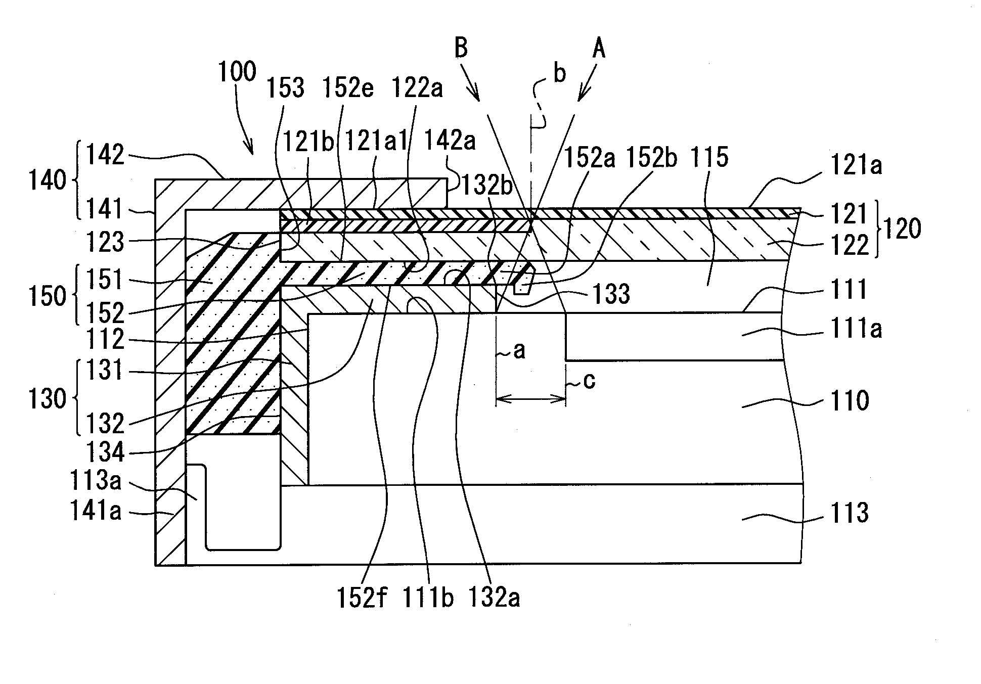
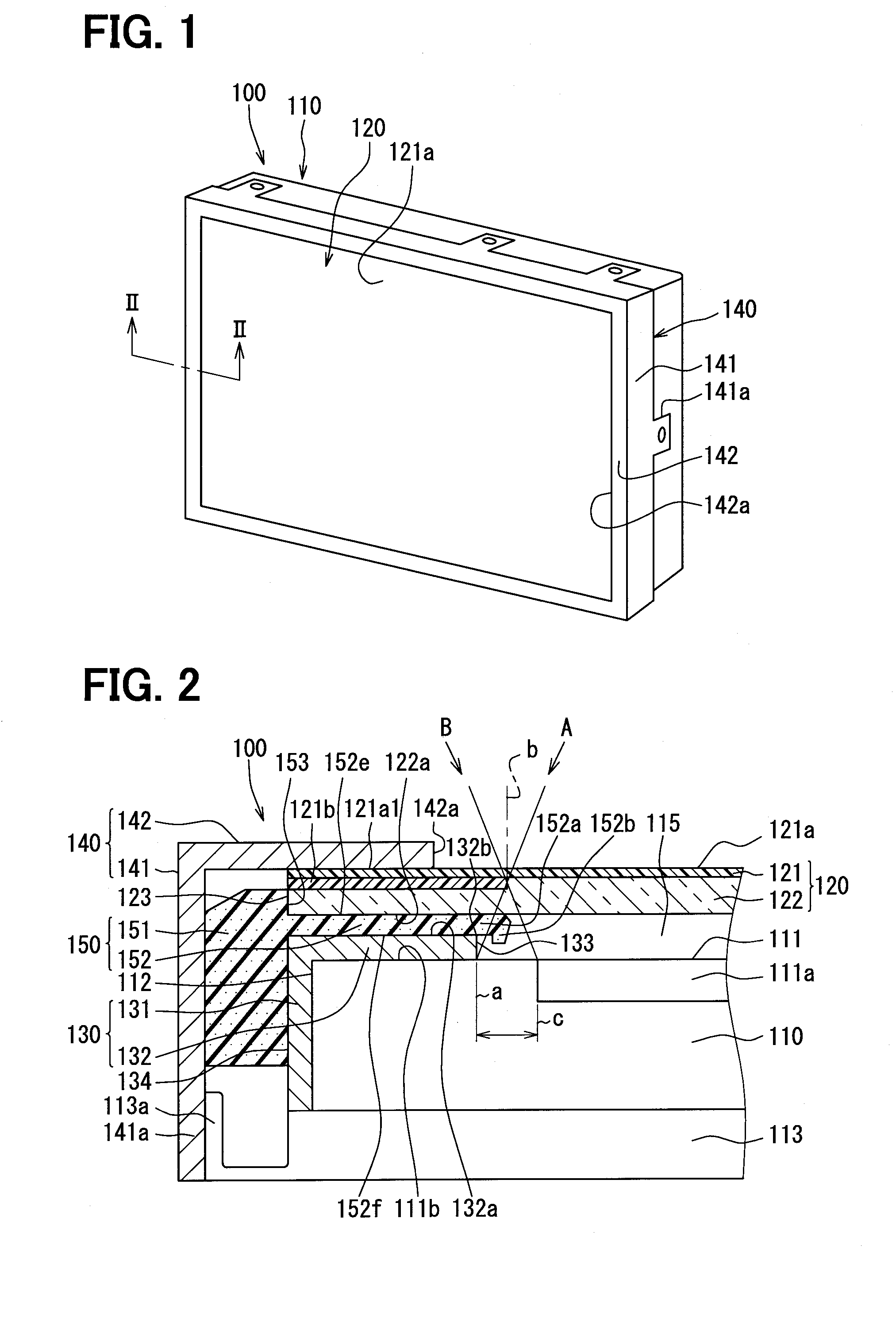
[0014]A display device 100 according to a first embodiment of the present disclosure will be described with reference to FIGS. 1 and 2. The display device 100 of the present embodiment is, for example, a display device, which has a touch panel and is applied to a navigation system for a vehicle. The display device 100 is placed at a location, such as an upper part of a center location of an instrument panel of the vehicle, where the display device 100 is easily viewable by a driver of the vehicle. The display device 100 displays a map, a current location and a traveling direction of the own vehicle on the map, and guidance information for a desirable destination on a display 110, as various information (predetermined information) at the car navigation system. The driver (a user) can perform an input operation for changing display content through a finger operation, such as finger touch, finger slide, on an operating surface 121a of a touch panel 120, thereby allowing the change of t...

second embodiment

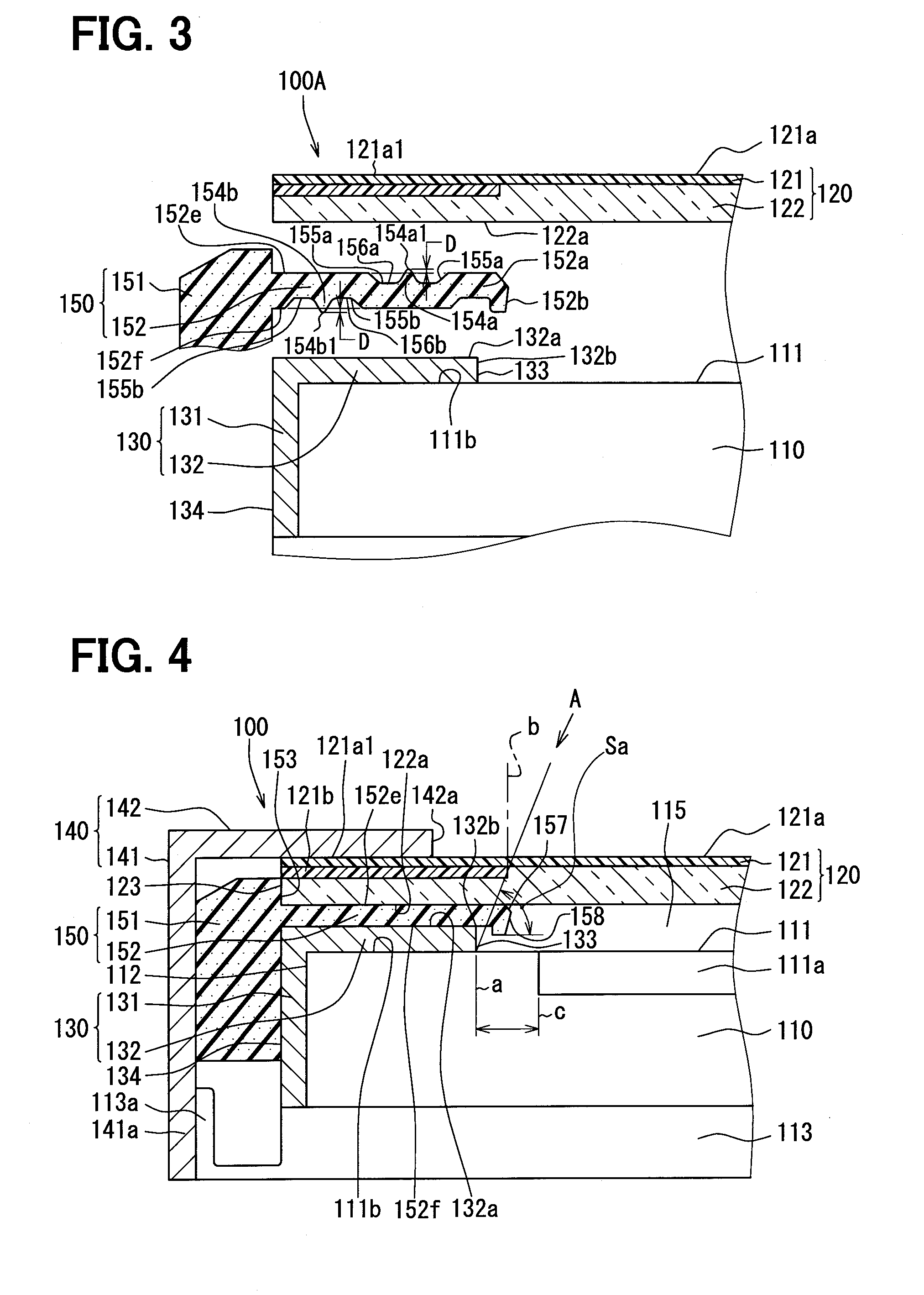
[0040]FIG. 3 shows a display device 100A according to a second embodiment of the present disclosure. The second embodiment is an embodiment, in which a touch panel side ridge 154a and a front case side ridge 154b (hereinafter also referred to as ridges 154a, 154b) are added to the insulator portion 152 in the first embodiment discussed above.

[0041]A touch panel side recess 156a is recessed in a surface (planar surface) 152e of the insulator portion 152, which is opposed to the touch panel 120. The touch panel side ridge 154a projects from a bottom surface of the touch panel side recess 156a toward the corresponding surface (the planar surface) 122a of the touch panel 120. A distal end part 154a1 of the touch panel side ridge 154a contacts the surface 122a of the touch panel 120 at an opening end of the touch panel side recess 156a. The touch panel side ridge 154a has a cross section that is tapered toward the distal end part 154a1 in a direction perpendicular to the surface 122a of ...


PUM


Abstract

A display device includes a display, which has a display surface, and a touch panel, which is spaced from and is opposed to the display surface. An opening of a panel frame portion-relative to the touch panel is formed to be larger than an opening of a front case relative to the display unit. An insulator portion extends toward a center of the opening of the front case beyond an inner peripheral part of the front case to mask the front case from eyesight of a user.

Description

CROSS REFERENCE TO RELATED APPLICATION[0001]The present disclosure is based on and incorporates herein by reference Japanese Patent Application No. 2013-16042 filed on Jan. 30, 2013 and Japanese Patent Application No. 2013-122921 filed on Jun. 11, 2013.TECHNICAL FIELD[0002]The present disclosure relates to a display device.BACKGROUND ART[0003]For instance, a display device disclosed in Patent Literature 1 is known as a prior art display device. In the display device of Patent Literature 1, a touch panel is placed on a side where a display surface of a display unit (LCD) is placed, and the display unit and the touch panel are received in a housing. An opening is formed in a surface of the housing, which is opposed to the touch panel. An operating surface of the touch panel is visible from the opening of the housing. Furthermore, a rubber frame is interposed between an outer peripheral portion of the display unit and an outer peripheral portion of the touch panel to form a predetermin...

Claims


Application Information

Patent Timeline
IPC IPC(8): G09G3/36G06F1/16G06F3/041
CPCG09G3/36G06F3/0412G06F2203/04103G06F1/1643G06F1/1626G06F3/041G09F9/00G02F1/13338G01C21/265
Inventor KITOH, KAZUOKAWASHITA, TSUBASA
Owner DENSO CORP
Why Eureka
Try Eureka