Conductor connection structure of laminated wiring body

a technology of connecting structure and wiring body, which is applied in the direction of fixed connection, coupling device connection, printed circuit non-printed electric component association, etc., to achieve the effect of simple structure and ease, without increasing the number of components

Active Publication Date: 2018-10-18
YAZAKI CORP
View PDF10 Cites 1 Cited by
  • Summary
  • Abstract
  • Description
  • Claims
  • Application Information

AI Technical Summary

Benefits of technology

[0005]The invention has been made in view of the circumstances, and an object thereof is to provide a conductor connection structure of a laminated wiring body having a plurality of stacked plate wiring members which can electrically connect a mating conductor to the plate wiring member of each layer wiring member even at positions on the way in an extending direction of the laminated wiring body wiring member with a simple structure and ease, without increasing the number of components.
[0012]According to the conductor connection structure of the laminated wiring body of the configuration (2), the raised piece formed in the plate wiring member of each layer wiring member passes through the insertion hole formed in the upper plate wiring member, so that the raised piece of each layer can protrude from the upper surface of the laminated wiring body. In other words, the connector portions of the plate wiring members of all the layers are taken out in the upper surface of the laminated wiring body. The insulating layer is removed from the periphery of the leading end of the raised piece of the taken-out plate wiring member, so that the taken-out plate wiring member is easily connected to the mating conductor such as a mating connector as a so-called card edge terminal. As a result, the leading ends of a plurality of raised pieces which are cut and raised in the plate wiring member of each layer wiring member can be directly used as the card edge terminal, so that a simple connection structure can be achieved, and also it is possible to prevent an increase of components in number.(3) For example, the connection portion is a contact surface provided in a partial region in an upper surface of the lower plate wiring member, the leading-out portion has exposure holes which are bored in both of the upper plate wiring member and the insulating layer to expose the contact surface to an upper surface of the laminated wiring body.
[0013]According to the conductor connection structure of the laminated wiring body of the configuration (3), the insulating layer is removed to form the contact surface in a partial region in the upper surface of the plate wiring member of each layer. The contact surface of the lower plate wiring member is exposed in the upper surface of the laminated wiring body through the exposure hole formed in the upper plate wiring member and the insulating layer. The contact surfaces of all the layers are exposed in the upper surface of the laminated wiring body and can be electrically connected to the mating conductor. The exposed contact surface of the plate wiring member of each layer wiring member can be connected in a state where a protruding abutting terminal (mating conductor) abuts on the leading end of an abutting connector for example. With this configuration, a conductor surface of the plate wiring member itself can be used as a contact surface with respect to the abutting connector, so that a simple connection structure can be achieved, and also it is possible to prevent an increase of components in number.(4) For example, the connection portion is a columnar fastening member erected in an upper surface of the lower plate wiring member, and the leading-out portion has insertion holes which are bored in both of the upper plate wiring member and the insulating layer to allow the fastening member to pass therethrough.
[0015]According to the conductor connection structure of the laminated wiring body of the configuration (5), the fastening member is erected in the plate wiring member. In at least one plate wiring member, the detour portion which is the leading-out portion is formed to be bent in the width direction of the plate wiring member and to come out of the overlapping area of the plate wiring members. The fastening member is erected in the upper surface of the detour portion. The fastening member erected in the detour portion of the plate wiring member is not overlapped with the other plate wiring member when the plate wiring members are overlapped. With this configuration, in the upper surface of the laminated wiring body, the plurality of fastening members are disposed in parallel in the width direction perpendicular to the extending direction of the laminated wiring body. The terminal (mating conductor) such as the mating electric wire is fastened to the fastening member. According to the conductor connection structure of the laminated wiring body, for example, a pair of fastening members connected to the positive electrode and the negative electrode can be provided in parallel in the width direction of the laminated wiring body which is relatively narrow. The insertion hole passing through the fastening member of the lower plate wiring member is not necessarily bored in the upper plate wiring member, so that it is possible to prevent that a cross section in the upper plate wiring member is reduced.(6) For example, the connection portion is a columnar fastening member erected in the lower plate wiring member, and the leading-out portion is a notched portion which is provided by cutting out one side edge in a width direction of the upper plate wiring member perpendicular to the extending direction of the plate wiring members to insert the fastening member therein.
[0017]According to the conductor connection structure of the laminated wiring body of the configuration (7), the plurality of plate wiring members become the laminated wiring body in which at least a pair of even layers are stacked. The expression “at least a pair of even layers” means two pairs of four layers or three pairs of six layers. In the laminated wiring body, one of the pair of the plate wiring members is connected to the positive electrode of the power source, and the other is connected to the negative electrode. With the conductor connection structure of the laminated wiring body, the laminated wiring body may be configured such that the mating conductor connected to the auxiliary component can be electrically connected to the upper plate wiring member and to the lower plate wiring member at an arbitrary position of the upper surface on the way in the extending direction. With this configuration, the positive electrode and the negative electrode of the power source can be easily connected to the mating conductors of the plurality of auxiliary components mounted at arbitrary positions of the vehicle in a short distance.
[0018]According to the conductor connection structure of the laminated wiring body of the invention, it is possible to electrically connect the mating conductor to the plate wiring member of each layer wiring member even at positions on the way in the extending direction of a laminated wiring body with a plurality of stacked plate wiring members with a simple structure and ease, without increasing the number of components.

Problems solved by technology

However, there are no other specific configurations except that the connector includes a tab terminal which protrudes to the side of the planar wiring body.

Method used


Image

  • Conductor connection structure of laminated wiring body
  • Conductor connection structure of laminated wiring body
  • Conductor connection structure of laminated wiring body

Examples


first embodiment

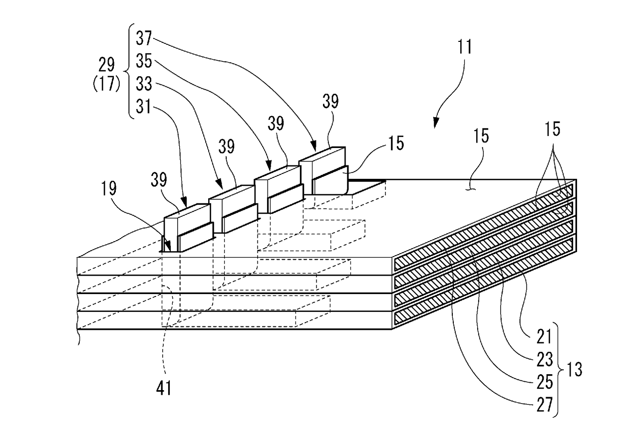
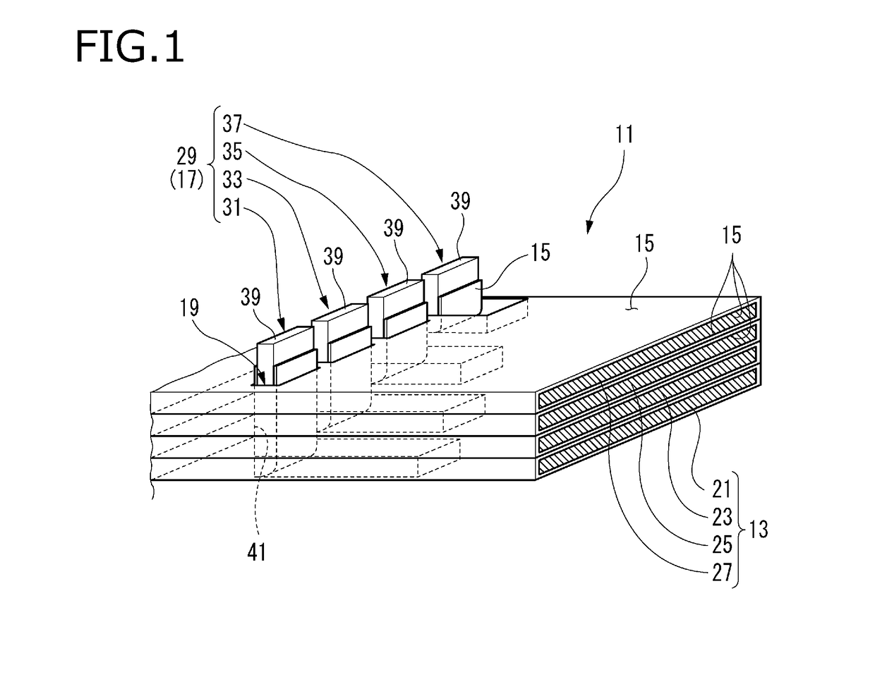
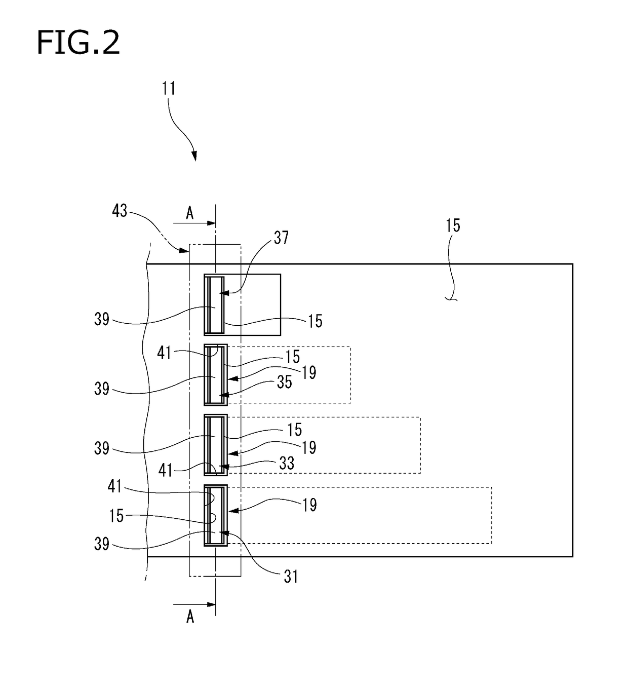
[0035]FIGS. 1 to 3 are a perspective view, a top view, and an exploded perspective view illustrating main parts of a laminated wiring body 11 which includes a conductor connection structure of a laminated wiring body according to a first embodiment of the invention. The conductor connection structure of the laminated wiring body according to the first embodiment mainly includes a plate wiring member 13, an insulating layer 15, a connection portion 17, and a leading-out portion 19.

[0036]The plate wiring member 13 is made of a conductive material, and formed by stacking a plurality of layers. The plurality of layers of the plate wiring member 13 are stacked through the insulating layer15 to form the laminated wiring body 11. The number of stacking layers of the plate wiring member 13 is not particularly limited. In other words, the laminated wiring body 11 may be formed of four layers as illustrated in the drawing, or may be two layers. In this embodiment, a first plate wiring member ...

second embodiment

[0062]Next, the description will be given about a second embodiment of a conductor connection structure of a laminated wiring body according to the invention. FIGS. 8 to 10 are a perspective view, a top view, and an exploded perspective view illustrating main parts of a laminated wiring body 71 provided with the conductor connection structure of the laminated wiring body according to the second embodiment of the invention. In the second embodiment, the same members as those described in the first embodiment are assigned with the same symbols, and the redundant description will be omitted. In the conductor connection structure of the laminated wiring body according to the second embodiment, the connection portion 17 of the laminated wiring body 71 becomes a contact surface 73 which is formed in a partial region in the upper surface of the plate wiring member 13.

[0063]The contact surface 73 is formed in a rectangular shape for example. The contact surface 73 may be formed by subjectin...

third embodiment

[0073]Next, the description will be given about a third embodiment of a conductor connection structure of a laminated wiring body according to the invention. FIG. 12 is a perspective view partially illustrating a laminated wiring body 103 provided with the conductor connection structure of the laminated wiring body according to the third embodiment of the invention together with a terminal 119 of an electric wire 105 (mating conductor). In the third embodiment, the same members as those described in the first embodiment are assigned with the same symbols, and the redundant description will be omitted.

[0074]In the conductor connection structure of the laminated wiring body according to the third embodiment, as illustrated in FIG. 12, the connection portion 17 of the laminated wiring body 103 is formed of a stud bolt 107 which is a columnar fastening member erected from the plate wiring member 13. In the third embodiment, the leading-out portion 19 is formed of an insertion hole 109 w...


PUM


Abstract

A conductor connection structure of a laminated wiring body includes a plurality of plate wiring members which are made of a conductive material and stacked to each other, an insulating layer which is arranged between the vertically-adjacent plate wiring members to insulate the vertically-adjacent plate wiring members, a connection portion which is provided in an upper surface of each of the plate wiring members on a way in an extending direction of the plate wiring members, and a leading-out portion which takes out the connection portion of a lower plate wiring member among the plurality of plate wiring member while avoiding an upper plate wiring member among the plurality of plate wiring member, the lower plate wiring member is arranged at a layer lower than the upper plate wiring member in the laminated wiring body.

Description

CROSS REFERENCE TO RELATED APPLICATIONS[0001]This application is based on Japanese Patent Application (No. 2017-079031) filed on Apr. 12, 2017, the contents of which are incorporated herein by reference.BACKGROUND OF THE INVENTION1. Field of the Invention[0002]The present invention relates to a conductor connection structure of a laminated wiring body.2. Description of the Related Art[0003]A laminated wiring body is known in which a plurality of stacked bus bars are provided to form a conductive path or a plurality of wiring bodies are stacked to form a planar wiring body (see JP-A-2011-146237 and JP-A-2016-101046). Such a laminated wiring body is useful in reducing impedance of the conductive path and in lessening an influence of noises while achieving space saving.[0004]However, in the laminated wiring body in the related art, a conductor (plate wiring member) of each layer is basically connected only at both ends. Therefore, there is a request that the plate wiring member of each...

Claims


Application Information

Patent Timeline
Patent Type & Authority Applications(United States)
IPC IPC(8): H01R12/55H01R12/72H05K1/02H05K1/11H05K1/18
CPCH01R12/55H01R12/72H05K1/0228H05K1/115H05K1/183H05K1/117H01R12/774H05K2201/09581H05K2201/09618H05K2201/092H05K2201/10295H05K2201/1034H01R11/12H05K2201/10409H01R25/00H01R13/2421H01R13/6273B60R16/0215H05K1/0298H05K3/202H05K3/4015H05K2201/10272
Inventor ITO, MASAHIROKAWAMURA, YUTAOKUDA, SADAHARU
Owner YAZAKI CORP
Why Eureka
Try Eureka