Enclosure for electric equipment and imaging device

a technology for enclosures and electronic equipment, applied in the field of enclosures for electronic equipment and imaging devices, can solve the problems of poor assembling performance, lack of designability, poor assembling performance, etc., and achieve the effect of preventing the inverse insertion of batteries, excellent assembling performance and heat transfer properties, and reducing the number of parts

Inactive Publication Date: 2010-12-07
FUJIFILM CORP
View PDF8 Cites 1 Cited by
  • Summary
  • Abstract
  • Description
  • Claims
  • Application Information

AI Technical Summary

Benefits of technology

[0011]The present invention has been made in view of the above circumstances and has an object to provide an enclosure for electronic equipment by extrusion molding which is excellent in assembling performance and heat transfer property and can ensure required strength without increasing the number of parts.
[0031]According to the present invention, an enclosure for electronic equipment which is excellent in assembling performance and heat transfer property and can ensure required strength can be provided by extrusion molding without increasing the number of components.

Problems solved by technology

The enclosure of Japanese Patent Application Laid-Open No. 2005-45025 is formed by extrusion molding, but since a box-shaped enclosure is made by combining plate-state members, there is a problem that assembling performance is poor.
Also, a joint between the members is seen from outside, which has a problem of lack in designability.
The enclosure of Japanese Patent Application Laid-Open No. 5-243751 has a structure in which only one rectangular cavity is formed inside the cylindrical member, and in order to incorporate a component inside, a member incorporating the component should be further assembled, which has a problem of poor assembling performance.
The enclosure of Japanese Patent Application Laid-Open No. 9-27682 incorporates a plurality of members incorporating components inside the cylindrical member extrusion-molded, which also has a problem of poor assembling performance similarly to the enclosure described in Japanese Patent Application Laid-Open No. 5-243751.

Method used


Image

  • Enclosure for electric equipment and imaging device
  • Enclosure for electric equipment and imaging device
  • Enclosure for electric equipment and imaging device

Examples


first embodiment

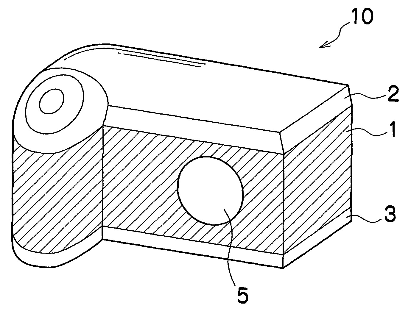
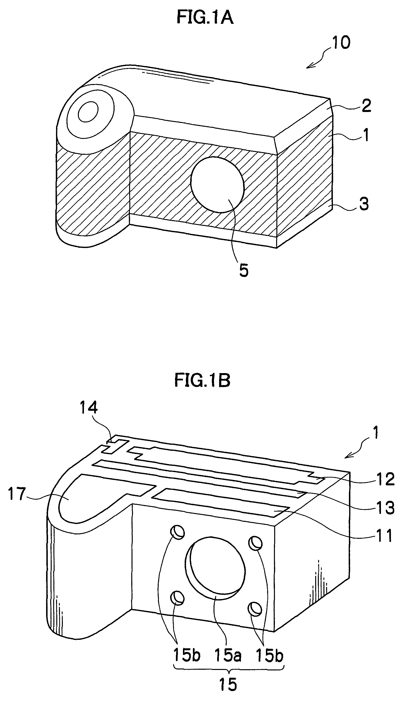
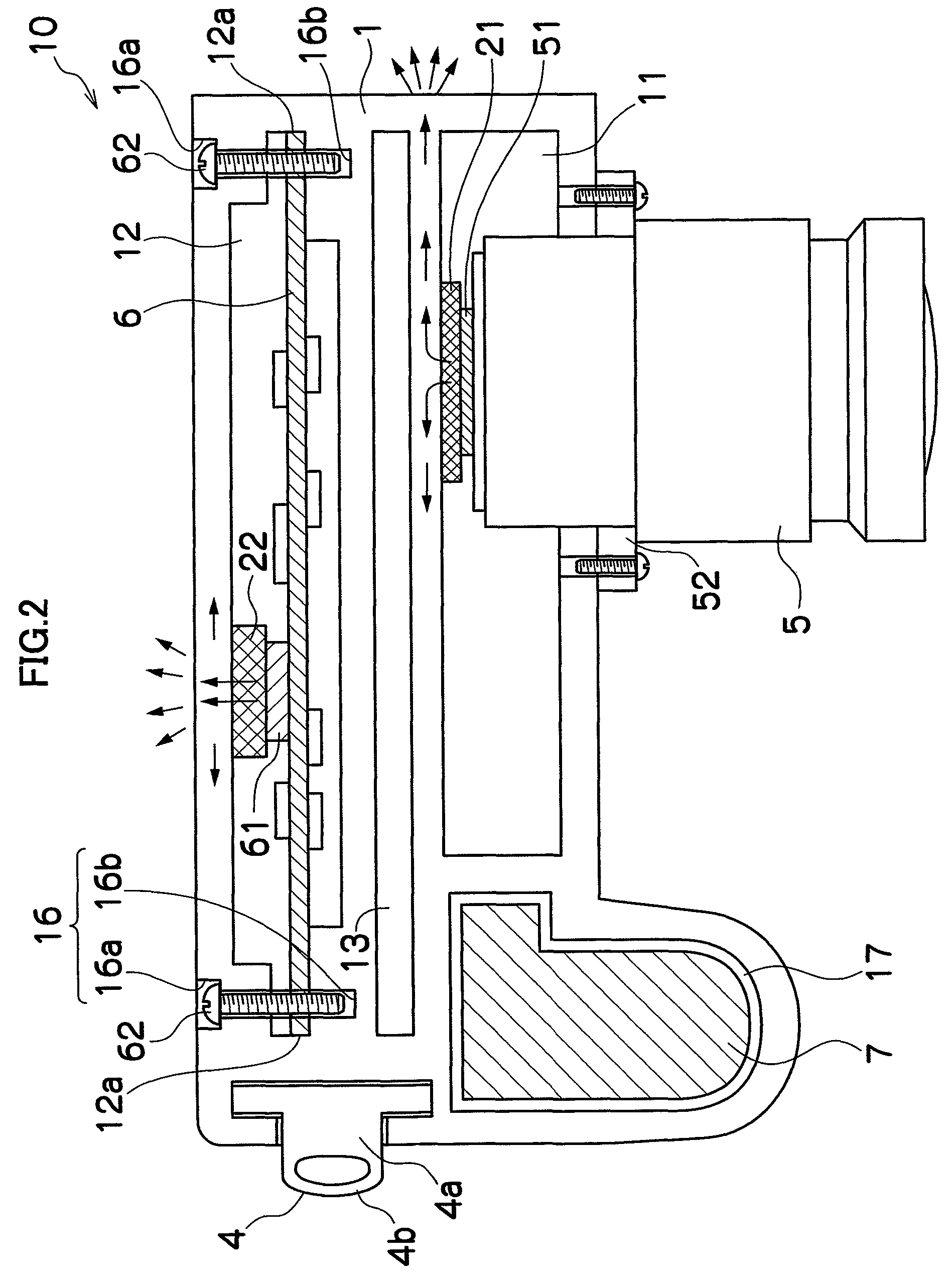
[0040]FIG. 1A is a perspective view of a digital camera 10 using a digital camera enclosure 1 according to a first embodiment of the present invention, and FIG. 1B is a perspective view of the digital camera enclosure 1. FIG. 2 is a perspective view of an essential part of the digital camera 10 using the digital camera enclosure 1.

[0041]The digital camera 10 mainly comprises the digital camera enclosure 1, an upper plate 2, a lower plate 3, a strap mounting member 4, and a lens barrel 5.

[0042]The digital camera enclosure 1 is formed of aluminum alloy and molded by extrusion molding by extrusion in the vertical direction of the enclosure (vertical extrusion). As the aluminum alloy used in the digital camera enclosure 1, Al—Mg—Si A6063, Al—Mn A3003, A3004 and the like excellent in extrusion performance, corrosion resistance and surface treatment performance can be used, considering strength, moldability, cost and the like. Various metal materials including magnesium alloy, stainless a...

second embodiment

[0072]A second embodiment is different from the first embodiment in mounting of the lens barrel, in which a decoration ring is used.

[0073]FIG. 5 is a partial sectional view of a digital camera enclosure 1′ of the second embodiment. The same reference numerals are given to the same portions as those in the first embodiment, and the description will be omitted.

[Structure of the Digital Camera Enclosure 1′]

[0074]A lens barrel mounting portion 15′ is formed by post machining on the wall on the front face side of the optical system accommodation portion 11 and constituted by a hole 15a′ having a diameter larger than the maximum diameter of the lens barrel 5′ and four screw holes 15b′ formed by post machining on the wall on the rear face side of the optical system accommodation portion 11 and used when the lens barrel 5 is fixed to the digital camera enclosure 1′. It is only necessary that the number of the screw holes 15b′ may be three or more and not limited to four.

[Mounting of Compone...

third embodiment

[0078]A third embodiment is different from the first and second embodiments in mounting of the lens barrel, in which mounting accuracy and mounting strength of the lens barrel are improved as compared with those in the first embodiment.

[0079]FIG. 6A is a partial sectional view of a digital camera enclosure 1″ of the third embodiment, FIG. 6B is a front view of a lens barrel mounting portion 15″, and FIG. 6C is a front view of a lens barrel 5″. The same reference numerals are given to the same portions as those in the first embodiment, and the description will be omitted.

[Structure of the Digital Camera Enclosure 1″]

[0080]The lens barrel mounting portion 15″ is formed by post machining and constituted by a hole 15a″ into which a body portion of the lens barrel 5″ can be fitted and screw holes 15b″ and 15c″ used when the lens barrel 5″ is fixed on the digital camera enclosure 1″.

[0081]The hole 15a″ is formed on the wall on the front face side of the optical system accommodation portio...


PUM


Abstract

According to an enclosure for electric equipment of an aspect of the present invention, the enclosure having the plurality of accommodation portions accommodating separate contents, respectively, can be formed by one molding without assembling a plurality of components, which can reduce the number of assembling processes. Also, formation by one component eliminates a gap which would be generated by assembling components, which can improve enclosure strength and designability and reduce manufacturing costs.

Description

BACKGROUND OF THE INVENTION[0001]1. Field of the Invention[0002]The present invention relates to an enclosure for electronic equipment and an imaging device and particularly to an enclosure for electronic equipment and an imaging device formed by extrusion molding.[0003]2. Description of the Related Art[0004]As an enclosure using a member made by extrusion molding, the following arts are disclosed.[0005]Japanese Patent Application Laid-Open No. 2005-45025 proposes an enclosure formed in a box shape by an extrusion molding member and a press molding member.[0006]Japanese Patent Application Laid-Open No. 5-243751 proposes an enclosure in which an end plate is mounted at both ends of a member formed in a cylindrical shape through a packing.[0007]Japanese Patent Application Laid-Open No. 9-27682 proposes an enclosure in which a plurality of members incorporating components are inserted and fitted inside a cylindrical member formed by extrusion molding.SUMMARY OF THE INVENTION[0008]The e...

Claims


Application Information

Patent Timeline
Patent Type & Authority Patents(United States)
IPC IPC(8): G03B17/02
CPCG03B17/02H04N5/2252H04N23/51
Inventor HASEGAWA, TAKESHI
Owner FUJIFILM CORP
Why Eureka
Try Eureka