Tong positioning and alignment device

a positioning and alignment device technology, applied in the direction of drilling pipes, directional drilling, borehole/well accessories, etc., can solve the problem of discarded threaded sections, etc., and achieve the effect of less effort and easy attachmen

Inactive Publication Date: 2006-09-12
HOBGOOD JOHN PAUL
View PDF11 Cites 19 Cited by
  • Summary
  • Abstract
  • Description
  • Claims
  • Application Information

AI Technical Summary

Benefits of technology

[0011]The present invention solved the problems in the art in a simple and straight forward manner. What is provided is an improved tong positioning and alignment apparatus which includes a base with a drip pan, designed to capture accidental oil spill or drip from the system, positionable on the rig floor; a hydraulic cylinder positioned on the base, having a first end engageable to a rear support member and a second end engageable to a pivotal moment arm; a forward shock attachment arm(s) engaged at a first end to one of three attachment points on the moment arm, and a second end which attaches to a tong frame attachment point(s) on the tong. The (single) moment arm may be bilaterally functional provided the system has a pivotal shaft extending outwardly on each side of the forward support member whereby the forward end of the moment arm actually has two forward ends, one each on each side of the forward support member and each having multiple bores thus emanating the structure for an additional forward shock absorber attached thereof.
[0012]Further, the tong frame is designed with a forward tong frame pivotal attachment member to accommodate a forward shock absorber on each side which additionally provides greater strength and stability during the torque process and further limits the bending and shearing effect of the tong while in tension with the tubular section. The greater the stress established through the bending and shearing effect applied to the threaded connection, the greater the probability the torque turn graph may display a bad connection thus the potential to discard that particular threaded section. Each forward shock attachment arm includes a pair of shock absorbers engaged along its length to provide a smooth, non-jerking motion both vertically and horizontally in moving the power tong. Each forward shock attachment arm may also be designed with more than two shock absorbers or the use of only one single shock absorber is desirable if the handling procedure with the size and weight of each power tong thus dictates the need for such. The tong positioning apparatus is designed to be remotely operated by hydraulic, air, air over hydraulics, electronically, hard wired or wireless or otherwise by a single operator. There is further provided a plurality of attachment points on the rear support member, and a plurality of pivot points for the moment arm, to allow for various vertical and horizontal positioning of the tong during makeup and breakup of pipe on the rig floor. Further, the apparatus includes a safety shield system to insure the workers are protected from inadvertent contact with moving parts of the apparatus.
[0013]Further there is provided a means for aligning the pipe within the tong apparatus by so that pipe, such as Chrome 13, or similar soft pipe, can be carefully guided into the tong, and eased in position, without the pipe wall making forceful contact with the tong. There is further provided at least two cameras which view the entire operation so that the manipulation of the pipe can be accomplished by an operator from a remote location.

Problems solved by technology

The greater the stress established through the bending and shearing effect applied to the threaded connection, the greater the probability the torque turn graph may display a bad connection thus the potential to discard that particular threaded section.

Method used


Image

  • Tong positioning and alignment device
  • Tong positioning and alignment device
  • Tong positioning and alignment device

Examples


Embodiment Construction

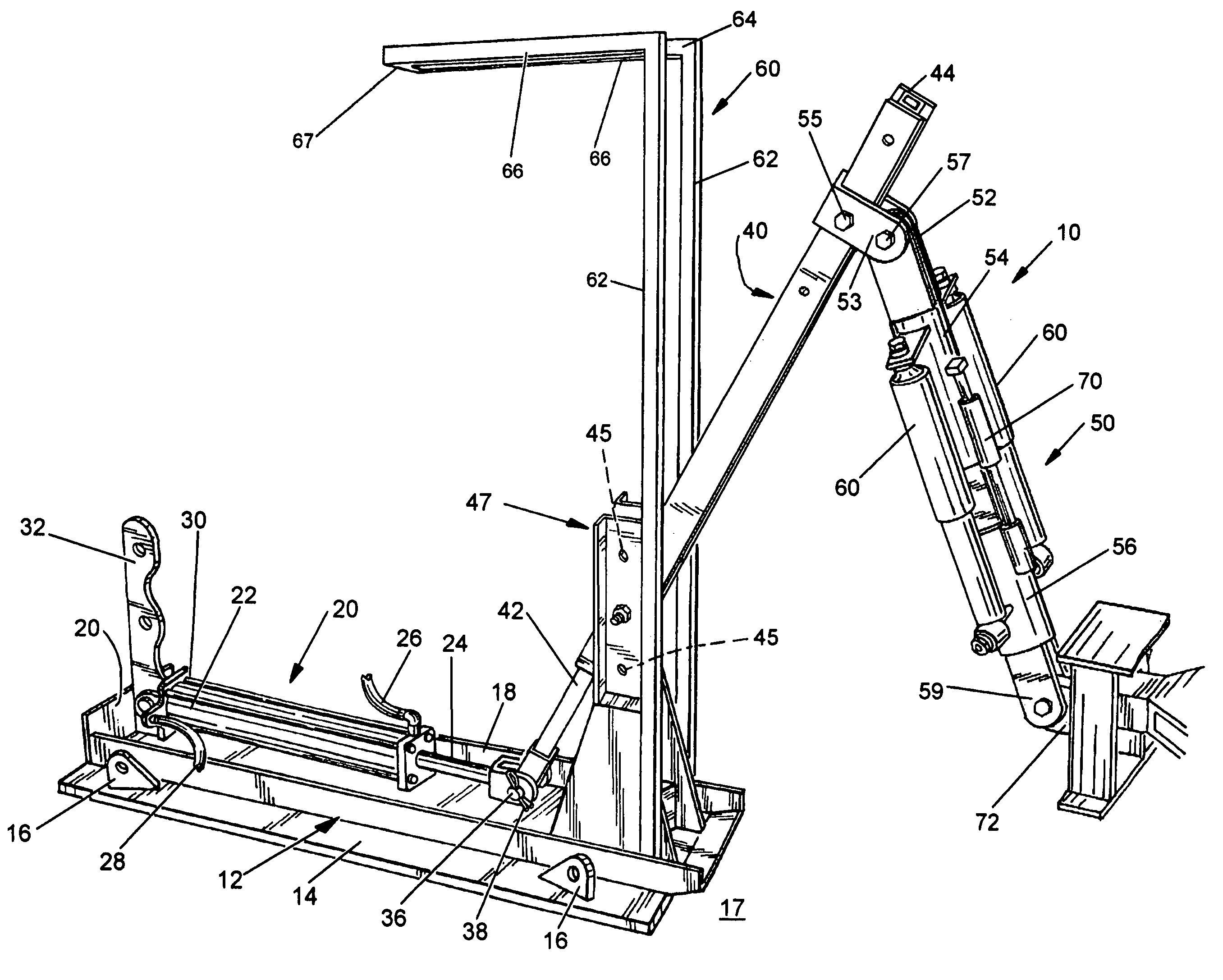
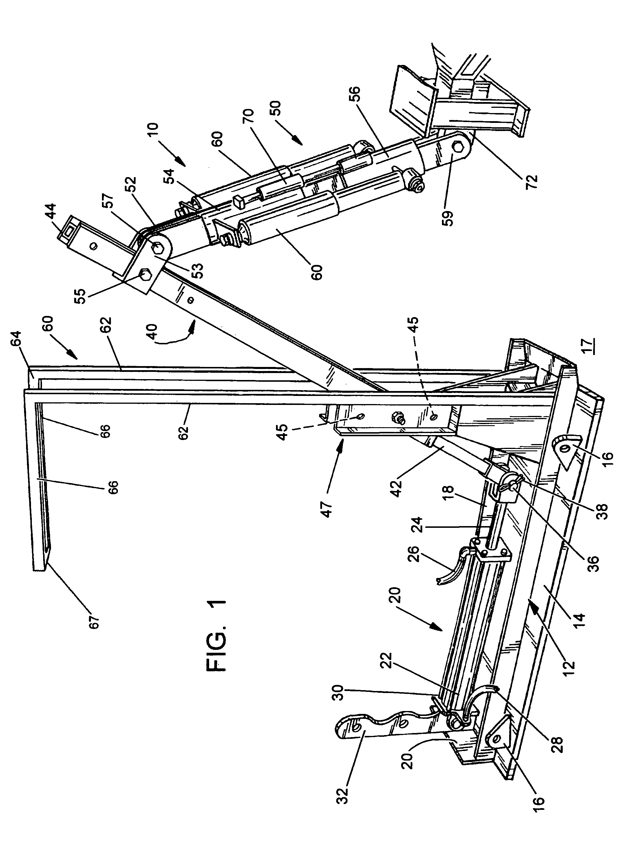
[0040]FIGS. 1 through 18 and 20 through 26 illustrate the preferred embodiment of the present invention; i.e., the improved tong positioning device (the “device”) by the numeral 10. FIG. 19 illustrates a prior art lift system for a power tong, so that the operation of the present invention may be more fully explained.

[0041]Turning first to the present invention, as illustrated in the various views, and in particular FIGS. 1 through 3, device 10 includes a base member 12 which comprises a flat base plate 14 of heavy iron or steel, having a lifting eye 16 at each corner for lifting device onto and off of a rig floor 17, and / or to aid in securing the device to the rig floor. There is further provided a rectangular container or box 18, having a plurality of walls 20, which would define a means for capturing any hydraulic or other type fluids which may be released from the device, and containing the fluids within the box 18, rather than the fluids flowing on the rig floor 17.

[0042]The re...


PUM


Abstract

An improved tong positioning apparatus which includes a base positionable on the rig floor; a hydraulic cylinder positioned on the base, having a first end engageable to a rear support member and a second end engageable to a pivotal moment arm; a forward shock attachment arm engaged at a first end to one of three attachment points on the moment arm, and a second end which attaches to a tong frame attachment point on the tong. The forward shock attachment arm includes a pair of shock absorbers engaged along its length to provide a smooth, non-jerking motion both vertically and horizontally in moving the power tong. The tong positioning apparatus is designed to be remotely operated by hydraulic, air, air over hydraulics, electronically, by a single operator. There is further provided a plurality of attachment points on the rear support member, and a plurality of pivot points for the moment arm, to allow for various vertical and horizontal positioning of the tong during makeup and breakup of pipe on the rig floor. Further, the apparatus includes a safety shield system to insure the workers are protected from inadvertent contact with moving parts of the apparatus. Further, the apparatus includes a pipe section guide, digital or VHS video taping capability and positioning and alignment system to further align the upper tong and lower tong in relation to the pipe sections when mating with the jaw-die of the upper tong and the jaw-die combination of the lower tong. Further to the safety of the deck members, the tong operator controls the operation of the forward door of the upper tong during the torque process.

Description

CROSS-REFERENCE TO RELATED APPLICATIONS[0001]Not applicableSTATEMENT REGARDING FEDERALLY SPONSORED RESEARCH OR DEVELOPMENT[0002]Not applicableREFERENCE TO A “MICROFICHE APPENDIX”[0003]Not applicableBACKGROUND OF THE INVENTION[0004]1. Technical Field of the Invention[0005]The present invention relates to oil field devices. More particularly, the present invention relates to an apparatus which has the ability to position and properly align a power tong around sections of oil field pipe on the rig floor by a single deck hand.[0006]2. General Background of the Invention[0007]In the drilling and completion phases in exploring for oil and gas, pipe tongs have been utilized for engaging lengths of drill or completion pipe, known generally as tubular members, end to end, by deck hands on the rig floor. A typical power tong comprises a first set of jaws which hold one section of pipe stationary while a second set of jaws rotate the next section to make up or break up the joint. The power ton...

Claims


Application Information

Patent Timeline
Patent Type & Authority Patents(United States)
IPC IPC(8): E21B19/16
CPCE21B19/165
Inventor HOBGOOD, JOHN PAUL
Owner HOBGOOD JOHN PAUL
Why Eureka
Try Eureka