Surgical Stapling Head Assembly with a Rotary Cutter

a rotary cutter and stapling head technology, applied in the field of surgical stapling head assembly, can solve the problems of comparatively large resistance and monotonous function, and achieve the effect of reducing resistance, ensuring surgical operation success, and shortening the backward journey

Active Publication Date: 2010-07-29
TOUCHSTONE INTERNATIONAL MEDICAL SCIENCE CO LTD
View PDF5 Cites 10 Cited by
  • Summary
  • Abstract
  • Description
  • Claims
  • Application Information

AI Technical Summary

Benefits of technology

[0009]The present invention has following advantages: by employing bearing structure, the annular cutter can be connected tight with the staple driver by mechanical structure, the annular cutter will not deviate from the central axis when the annular cutter forwards in way of helix, the section of tissues cut in surgery operations are in shape of full circle so as to avoid the potential danger of the cutter being stuck and unmovable, the surgery operations is ensured successful. Moreover, during the operation process, the annular cutter rotatingly forwards along the helix track when going forward, and backwards to the inner cavity of the staple holder in way of straight line or part of straight line under the guide from the backward track, the operation of forwarding and retreating which is previously realized by one helix track is divided into two parts, the helix track undertakes the forward operation and the backward track undertakes the backward operation, the forward helix track is communicated with the backward track to form at least one back and forth journey, which shortens the backward journey and reduces the resistance subjected by the annular cutter when retreating, the time consumed for retreating is reduced as well, therefore, the surgery operations can be implemented more easily with more safety.

Problems solved by technology

A circular stapling instrument is used for performing a circular anastomosis stapling operation, unwanted tissues are cut while suturing, however, the annular cutter of prior art works in way of straight forward and straight backward thereby the doctor has to exert large force when doing the operation so that tissues are able to be cut by impulsive force, sometimes the tissues may not be cut completely and the uncut tissues will be stretched to break by the force from the stapling instrument while retreating, which brings tensile damages to anastomosis ring and the result is serious.
However, tracks for rotary cutting have comparatively monotonous function, the same helix tracks function not only as forward tracks but also function as backward tracks, the annular cutter has to rotate to retreat and it suffers comparatively large resistance because the backward journey is comparatively long.

Method used


Image

  • Surgical Stapling Head Assembly with a Rotary Cutter
  • Surgical Stapling Head Assembly with a Rotary Cutter
  • Surgical Stapling Head Assembly with a Rotary Cutter

Examples


first embodiment

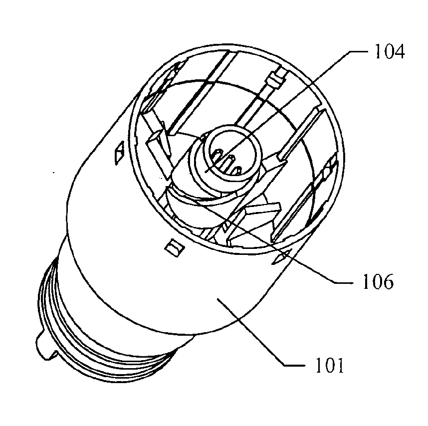
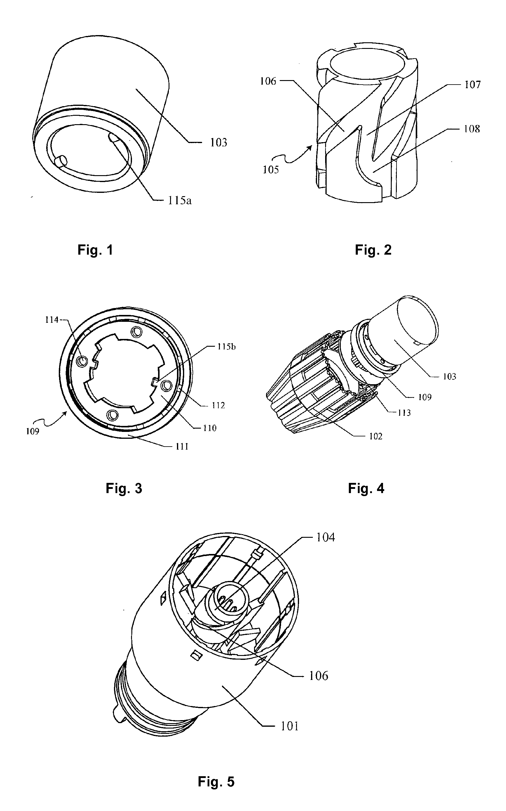
[0020]A surgical stapling head assembly with a rotary cutter as illustrated from FIGS. 1 to 5 comprises a casing 101, a staple driver 102, an annular cutter 103 and a staple holder, the casing 101 is a tubular body with a stepped inner cavity and an anti-expansion tube 104 is disposed therein, a plurality of staple pushers are arranged annularly and alternately in two rows, and are disposed between the anti-expansion tube 104 and the inner wall of the casing 101, the staple driver 102 is disposed at the proximal end of the staple pushers, the staple holder is disposed at the distal end of the staple pushers, the annular cutter 103 is disposed in the space formed by the inner wall of the staple holder.

[0021]A metal cylinder member 105 is molded on the outer wall of the anti-expansion tube 104, of which the structure is illustrated in FIG. 2, a forward helix track 106 and a backward track are distributed on the outer wall of the metal cylinder member 105, a guiding structure is dispos...

second embodiment

[0025]A surgical stapling head assembly with a rotary cutter as illustrated from FIGS. 1 to 5, of which the structure is similar to that in the first embodiment. The staple driver 102 is internal injection molded and fixed with the bearing structure 109, the bearing structure 109 comprises the bearing inner ring 110 and the bearing outer ring 111, the ball 112 is disposed between the bearing inner ring 110 and the bearing outer ring 111 as a transmission part. When the friction between the bearing inner ring 110 and the bearing outer ring 111 is not large, the bearing inner ring 110 is able to be connected with the bearing outer ring 111 by means of friction without the ball 112 or other transmission parts disposed between the bearing inner ring 110 and the bearing outer ring 111.

[0026]As another configuration of the guiding structure, guiding projections 115b are disposed inside the bearing inner ring 110 as the guiding structure, as illustrated in FIG. 3, the guiding projection 11...

third embodiment

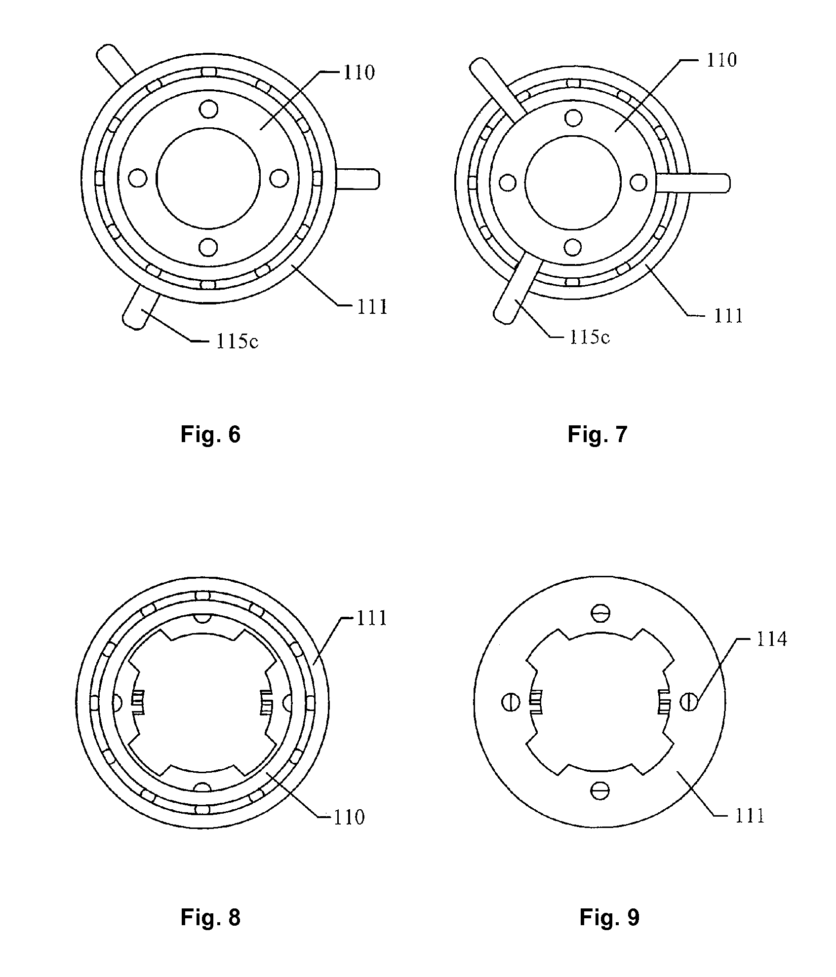
[0029]A surgical stapling head assembly with a rotary cutter as illustrated from FIGS. 1 to 9, of which the structure is similar to that in the first embodiment and second embodiment, the differences are that: the metal cylinder member 105 configured as illustrated in FIG. 2 is molded on the inner wall of the casing 101 (not shown in figures), guiding projections 115c are disposed on the bearing outer ring 111 or the outside of the bearing inner ring 110, as illustrated in FIGS. 6 and 7, alternatively, guiding projections 115c are disposed on the outside of the annular cutter 103 (not shown in figures), the guiding projections are set to engage with the helix forward track and backward track of the metal cylinder member 105.

[0030]For sake of easy combining and connecting, rivet holes 114 are disposed on said bearing inner ring 110 and connecting holes are disposed on the annular cutter 103 so that the bearing inner ring 110 and the annular cutter 103 can be fixed through rivets ther...


PUM

PropertyMeasurementUnit
angleaaaaaaaaaa
angleaaaaaaaaaa
forceaaaaaaaaaa

Abstract

http://www.wipo/int/pctdb/images/PCT-IMAGES/31122008/CN2008001226_31122008_gz_en.×4-b.jpg
A surgical stapling head assembly with a rotary cutter comprises a casing (101), an annular cutter (103), a staple driver (102) and a staple holder. Said staple driver (102) is connected with the annular cutter (103) by a bearing structure (109) with guiding projections (115a, 115b, 115c) disposed thereon, on the outer wall of the anti-expansion tube (104) or the inner wall of the casing (101) is molded with a metal cylinder member (105), on which is provided with a forward helix track (106) and a backward track (107) independent and communicated with each other, the guiding projections (115a, 115b, 115c) engaging with the two guiding tracks (106, 107) to guide the annular cutter (103) to forward in way of helix.

Description

FIELD OF THE INVENTION [0001]The present invention relates to a surgical stapling head assembly, more particularly, to a rotary cutter for surgical stapling head assembly in the technical field of medical instrument.BACKGROUND OF THE INVENTION[0002]A surgical stapling head assembly is the medical instrument used for performing a circular anastomosis stapling operation, which can be operated easily and the surgery operation time can be effectively reduced. The surgical stapling head assembly has distinct advantages over the manual suture, which is approved by more and more doctors and patients. A circular stapling instrument is used for performing a circular anastomosis stapling operation, unwanted tissues are cut while suturing, however, the annular cutter of prior art works in way of straight forward and straight backward thereby the doctor has to exert large force when doing the operation so that tissues are able to be cut by impulsive force, sometimes the tissues may not be cut c...

Claims


Application Information

Patent Timeline
Patent Type & Authority Applications(United States)
IPC IPC(8): A61B17/068
CPCA61B17/072A61B2017/07285A61B17/32053A61B17/115
Inventor CHEN, WANGDONGXU, WEIXIE, SHOUYE
Owner TOUCHSTONE INTERNATIONAL MEDICAL SCIENCE CO LTD
Why Eureka
Try Eureka