Fuel cell

Inactive Publication Date: 2010-07-29
KK TOSHIBA
View PDF7 Cites 19 Cited by
  • Summary
  • Abstract
  • Description
  • Claims
  • Application Information

AI Technical Summary

Benefits of technology

[0016]However, in a conventional internal-vaporization type DMFC, in order to evenly supply liquid fuel to the entire surface of the MEA fuel electrode, a distribution plate is disposed immediately in front of a gas-liquid separation film in a vaporizing chamber, and liquid fuel is circulated in a plurality of branch channels formed in the distribution plate. However, because pr

Problems solved by technology

However, because pressure losses in branch channels are great, high pump backpressure is required, resulting in considerable load on the pump.
If pump backpressure is excessive, air bubbles may easily

Method used


Image

  • Fuel cell
  • Fuel cell
  • Fuel cell

Examples


first embodiment

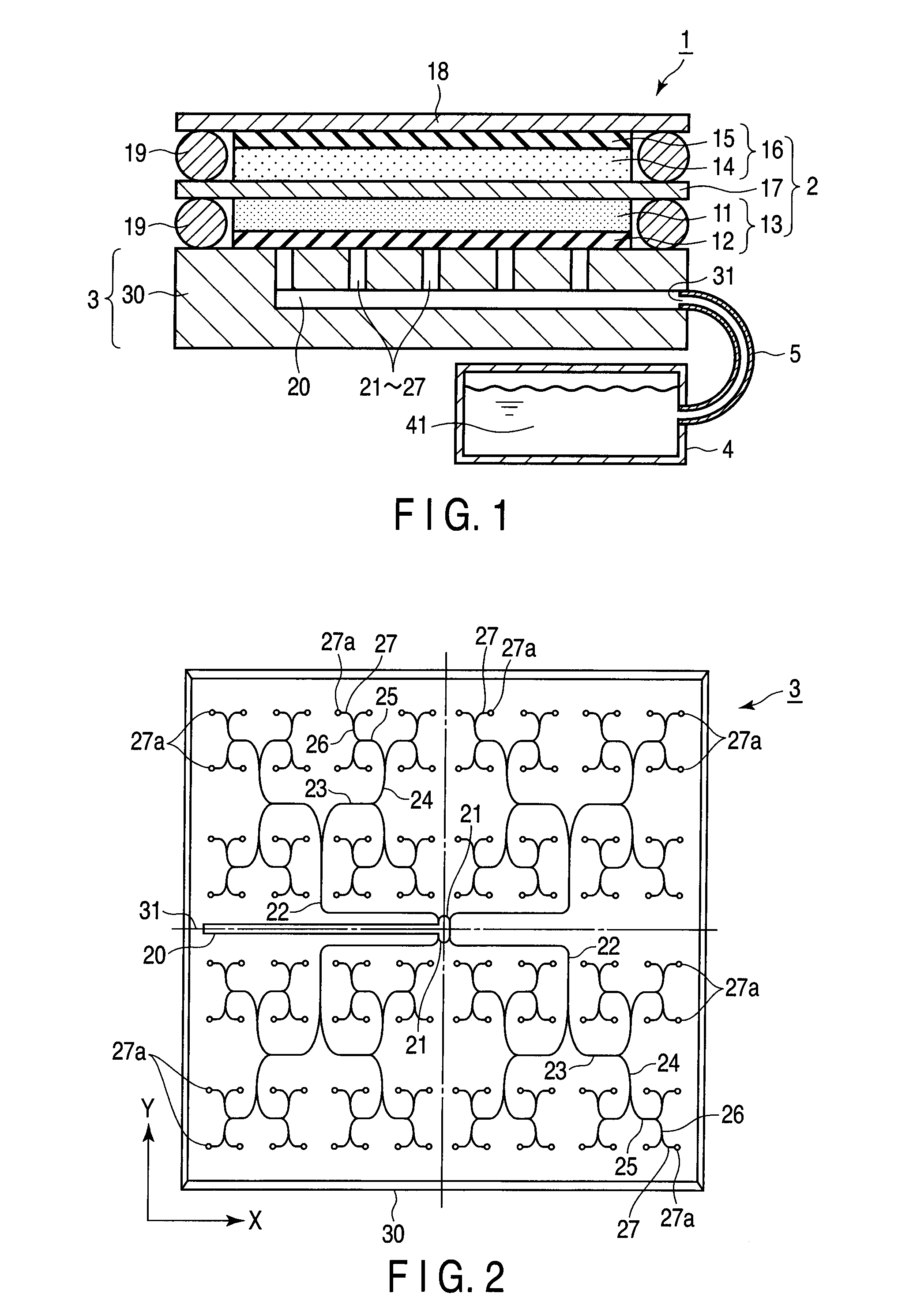
[0059]First, the schematic outline of the overall fuel cell will be described with reference to FIG. 1.

[0060]A fuel cell 1 according to a first embodiment is covered with an outer case 18 and a distribution plate 30 of a fuel distribution mechanism 3, and a membrane electrode assembly (MEA) 2 is accommodated in the fuel cell 1. The outer case 18 and the distribution plate 30 are screwed together, with the MEA 2 sandwiched therebetween, and the ends of the outer case 18 are caulked to the distribution plate 30, thereby integrating them. A pair of O-rings 19 is disposed on the periphery of the MEA 2, thereby sealing the space between the outer case 18 and MEA 2 and also the space between the distribution plate 30 and MEA 2, thus preventing fuel inside from leaking.

[0061]The MEA 2 is a power generating element that has a multi-polar structure including a plurality of strips of single electrodes (unit cells) arranged on substantially the same flat surface and electrically connected in s...

second embodiment

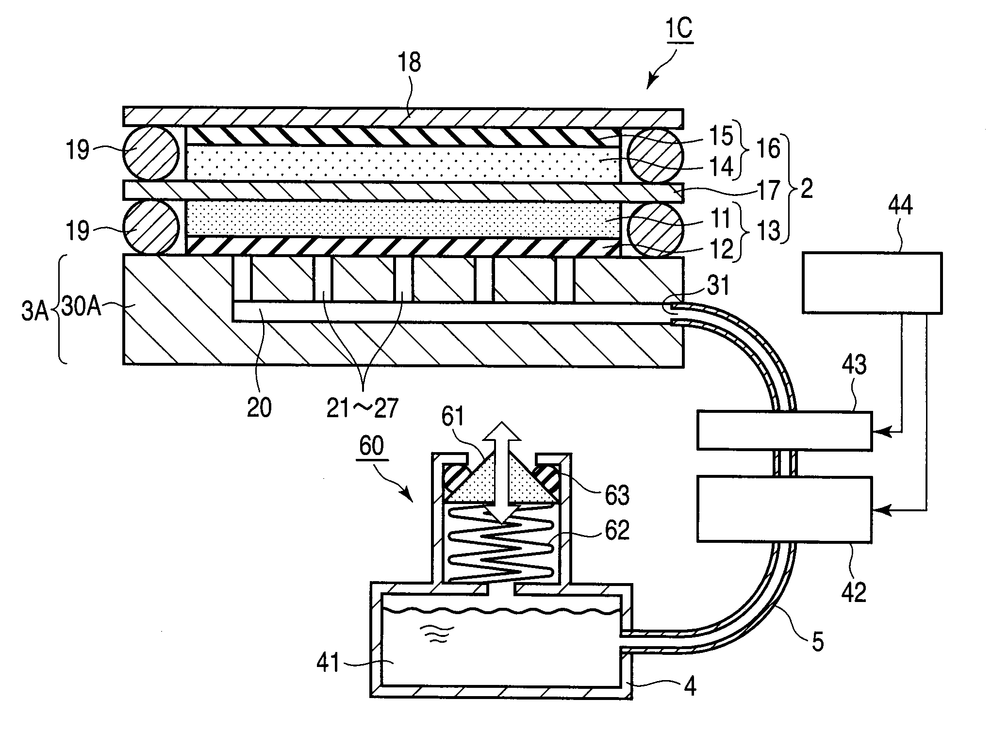
[0097]Referring to FIGS. 6 to 12, the second embodiment will next be described. Explanations of parts identical to those in the first embodiment are omitted.

[0098]As shown in FIG. 6, a fuel cell 1A according to the present embodiment comprises a fuel distribution mechanism 3A different from that of the fuel cell 1 in the first embodiment. As shown in FIG. 7, the fuel cell distribution mechanism 3A comprises a distribution plate 30A. The distribution plate 30A comprises: one fuel inlet 31; a plurality of fuel outlets 27a for discharging fuel toward an anode 13; and fuel passages 20 to 27 communicating with one another in order to circulate fuel from the fuel inlet 31 to the fuel outlets. The fuel passage comprises: an introduction tube 20 communicating with the fuel inlet 31; upstream fuel passages 21 communicating with the introduction tube 20; and first to sixth branch passages 22 to 27 diverging one after another in sequence from the upstream fuel passages 21. The fuel inlet 31 co...

example

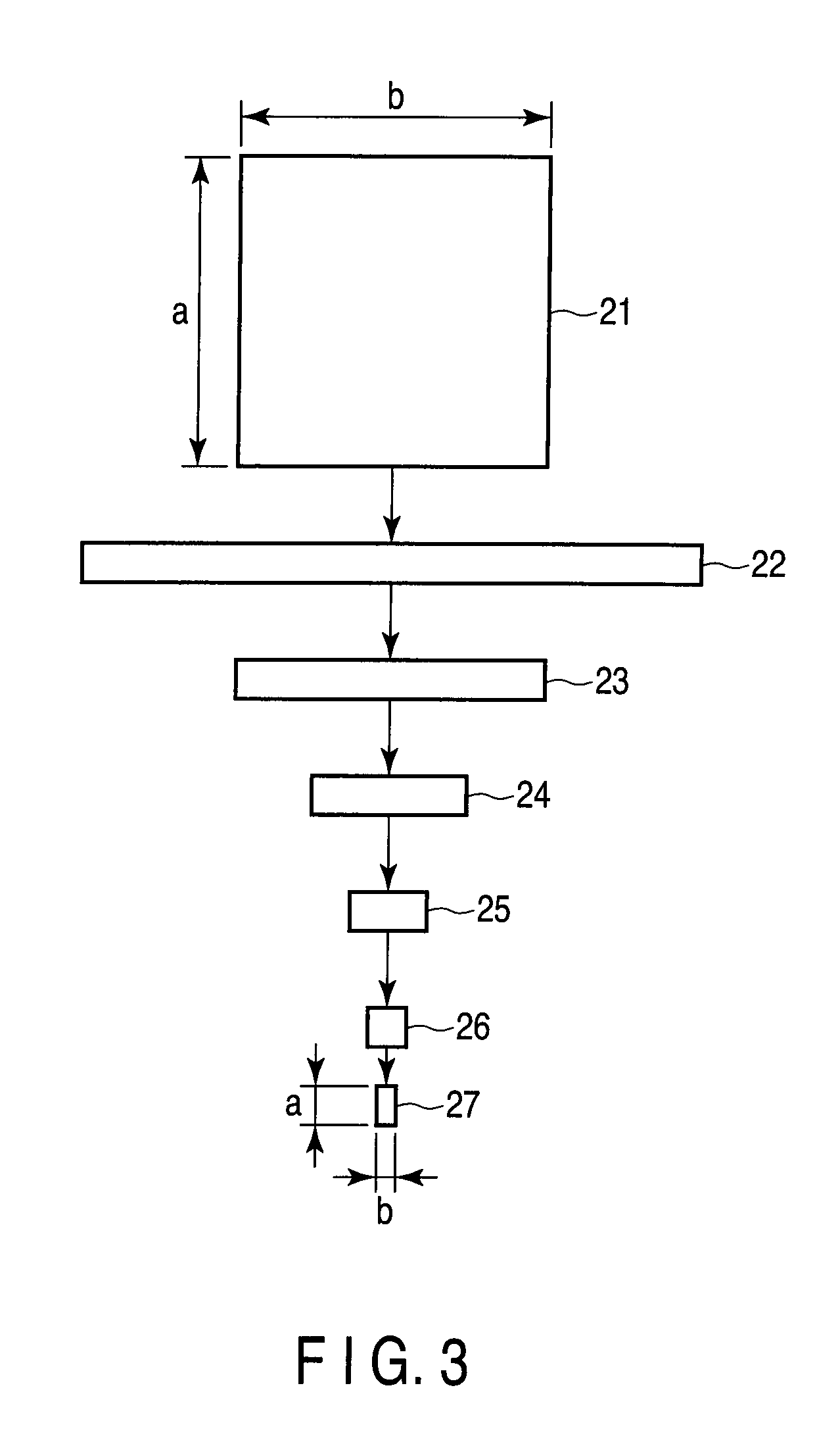
[0119]The present Example uses a fuel distribution mechanism 3 that has the same disposition of the fuel passages 20 to 27 shown in FIG. 7. An introduction tube 20 has a square cross-section of 400-μm height×400-μm width×400-μm length. The inside of each upstream fuel passage 21 is partitioned into four branch passages 21a to 21d, as shown by (a) in FIG. 3 and the Table 1, so as to have a cylindrical section with a diameter of 100 μm and a length of 45 mm.

[0120]The first branch passage 22 is 25 mm long and has a rectangular cross-section whose height “a” is 50 μm and width “b” is 800 μm. The second branch passage 23 is 14 mm long and has a rectangular cross-section whose height “a” is 50 μm and width b is 400 μm. The third branch passage 24 is 5 mm long and has a rectangular cross-section whose height “a” is 50 μm and width “b” is 200 μm. The fourth branch passage 25 is 6 mm long and has a rectangular cross-section whose height “a” is 50 μm and width “b” is 100 μm. The fifth branch ...


PUM


Abstract

A fuel distribution mechanism of a fuel cell, including a fuel inlet communicating with the supply channel, a plurality of fuel outlets which are open so as to be opposite the fuel electrode, and a fuel passage communicating with the fuel inlet and the fuel outlets in order to circulate the fuel from the fuel inlet to the fuel outlets, and the fuel passage is formed between the fuel inlet and the fuel outlets and comprises a plurality of branch passages that are adjusted in passage cross-sectional shape and branch structure as the branch passages extend from upstream to downstream between the fuel passage situated upstream and the fuel outlets and that have a desired channel resistance.

Description

CROSS REFERENCE TO RELATED APPLICATIONS[0001]This is a Continuation Application of PCT Application No. PCT / JP2008 / 067033, filed Sep. 19, 2008, which was published under PCT Article 21(2) in Japanese.[0002]This application is based upon and claims the benefit of priority from prior Japanese Patent Applications No. 2007-242948, filed Sep. 19, 2007; and No. 2008-001426, filed Jan. 8, 2008, the entire contents of both of which are incorporated herein by reference.BACKGROUND OF THE INVENTION[0003]1. Field of the Invention[0004]The present invention relates to a fuel cell disposed in a surface, which is effective to operate a mobile apparatus, and more particularly to an internal-vaporization type direct methanol fuel cell (DMFC).[0005]2. Description of the Related Art[0006]In recent years, various types of electronic device such as personal computers and mobile telephones have been reduced in size as semiconductor technology advances, and there have been attempts to use a fuel cell as th...

Claims


Application Information

Patent Timeline
IPC IPC(8): H01M8/10
CPCH01M8/04186H01M8/04201Y02E60/50H01M2008/1095H01M8/1011
Inventor YOSHIDA, YUICHIHASEBE, HIROYUKINEGISHI, NOBUYASUKAWAMURA, KOICHI
Owner KK TOSHIBA
Why Eureka
Try Eureka