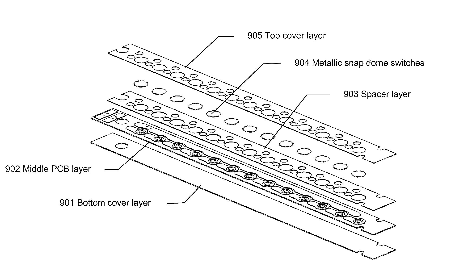
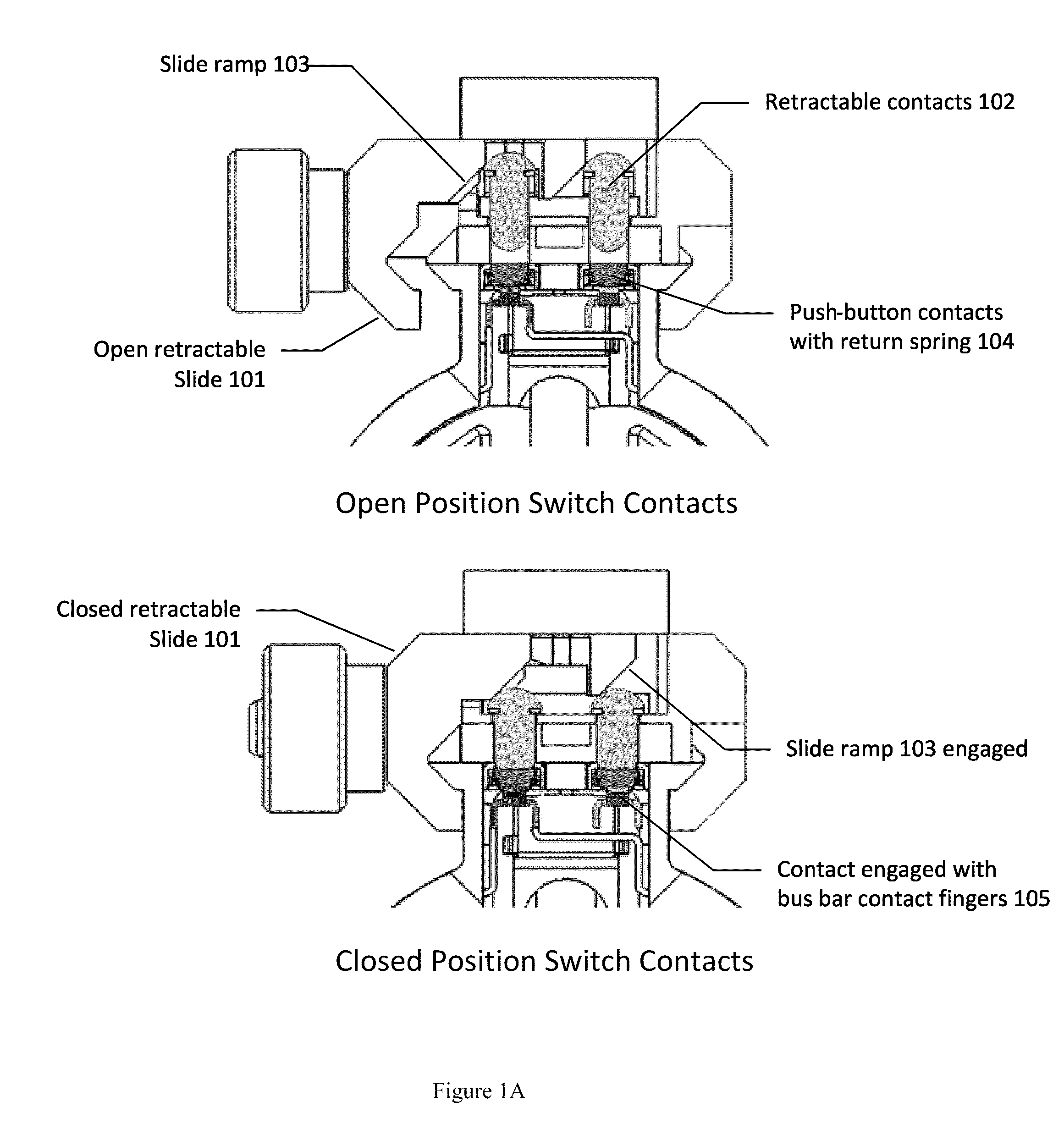
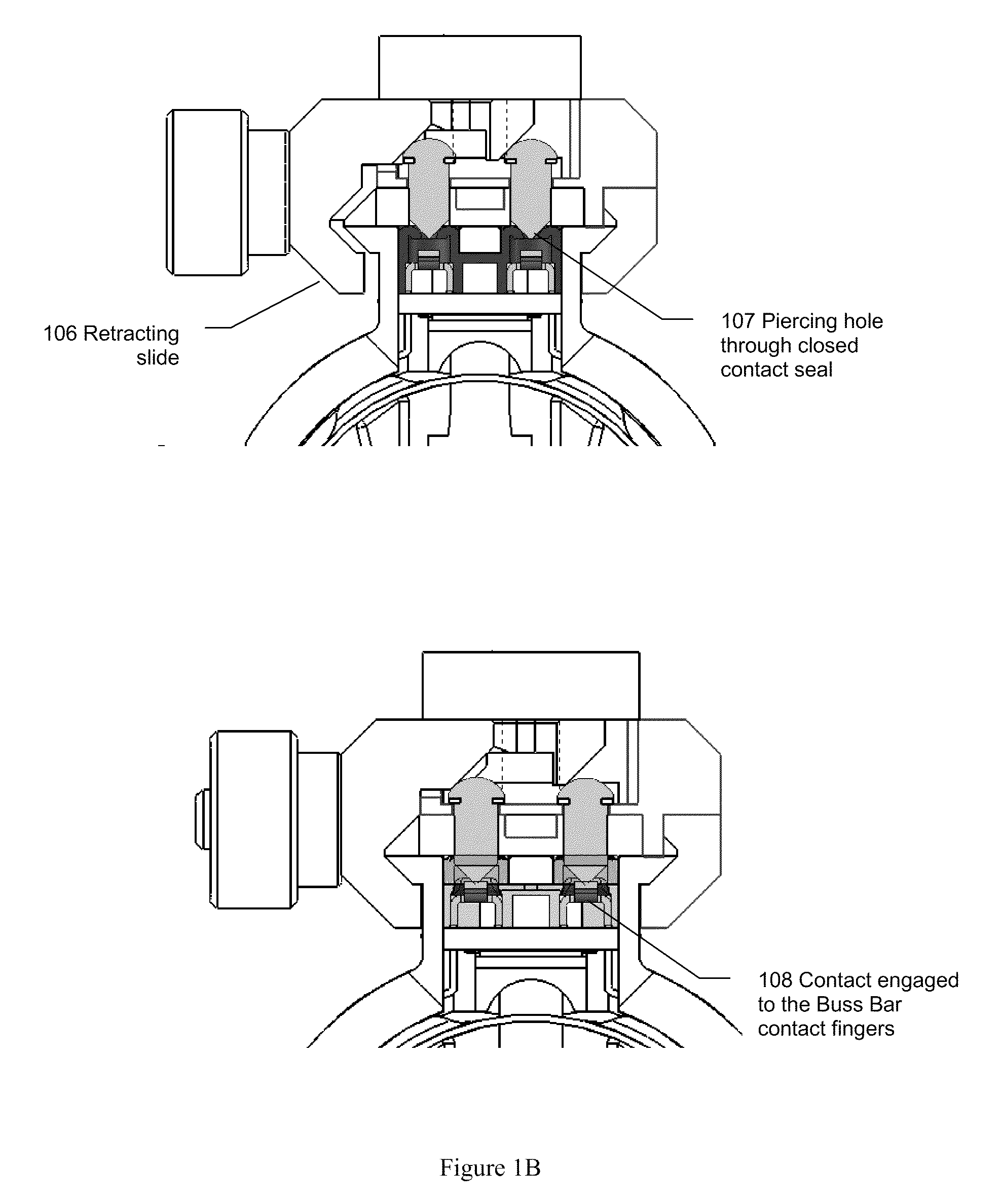
Rifle accessory rail, communication, and power transfer system - rail contacts

a technology of communication and power transfer system, applied in the field of weapons systems, can solve the problem of affecting the effectiveness of soldiers in the final stag

Active Publication Date: 2010-08-05
T WORX HLDG LLC
View PDF55 Cites 115 Cited by
  • Summary
  • Abstract
  • Description
  • Claims
  • Application Information

AI Technical Summary

Benefits of technology

[0004]It is an object of the present invention to obviate or mitig

Problems solved by technology

The result is a heavy weapon and a heavier field load of batteries to accommodate the various ac

Method used


Image

  • Rifle accessory rail, communication, and power transfer system - rail contacts
  • Rifle accessory rail, communication, and power transfer system - rail contacts
  • Rifle accessory rail, communication, and power transfer system - rail contacts

Examples


Embodiment Construction

[0032]For simplicity and illustrative purposes, the principles of the present invention are described by referring to various exemplary embodiments thereof. Although the preferred embodiments of the invention are particularly disclosed herein, one of ordinary skill in the art will readily recognize that the same principles are equally applicable to, and can be implicated in other compositions and methods, and that any such variation would be within such modifications that do not part from the scope of the present invention. Before explaining the disclosed embodiments of the present invention in detail, it is to be understood that the invention is not limited in its application to the details of any particular embodiment shown, since of course the invention is capable of other embodiments. The terminology used herein is for the purpose of description and not of limitation. Further, although certain methods are described with reference to certain steps that are presented herein in cer...


PUM


Abstract

The present invention is related to weapons systems. In particular, the present invention is directed to accessory attachment systems for rifles and small arms weapons that enable attached accessory devices to draw power from a central power source and communicate with the user and/or other devices.

Description

BACKGROUND OF THE INVENTION[0001]The present invention is related to weapons systems. In particular, the present invention is directed to accessory attachment systems for rifles and small arms weapons that enable attached accessory devices to draw power from a central power source and communicate with the user and / or other devices.[0002]The current rifles and small arm weaponry in use by US armed forces can be equipped with numerous combat optics, laser designators / sights, and flashlights; all comes with different power requirements and battery supplies. The result is a heavy weapon and a heavier field load of batteries to accommodate the various accessories, which ultimately impacts the soldiers' effectiveness, particularly on longer missions. One of the US Army focus areas is improving the performance of their warfighters' combat equipment while reducing the load that each warfighter has to carry. One of these efforts is concentrated on providing advanced technologies to demonstra...

Claims


Application Information

Patent Timeline
IPC IPC(8): F41C23/22F41C27/00
CPCF41G11/003F41G1/387
Inventor CABAHUG, ERICFELDMAN, BENSCHROEDER, JOHNDODD, JAMESTILTON, JAYMCLAUGHLIN, DONALDTAPIA, HECTOR
Owner T WORX HLDG LLC
Why Eureka
Try Eureka