Elastic shear band with cylindrical elements

a cylindrical element and shear band technology, applied in the field of shear bands, can solve the problems of unsuitability of elastomeric materials for certain applications, certain limitations of use of such materials,

Inactive Publication Date: 2010-08-05
MICHELIN RECH & TECH SA
View PDF10 Cites 62 Cited by
  • Summary
  • Abstract
  • Description
  • Claims
  • Application Information

AI Technical Summary

Benefits of technology

[0006]In another exemplary embodiment, the present invention provides a wheel that defines axial, radial, and circumferential directions. The wheel includes a hub, a shear band, and a plurality of support elements connected between the hub and the shear band. The shear band includes an outer circumferential member extending along the circumferential direction at a radial position R2, and an inner circumferential member e

Problems solved by technology

The use of such materials has certain limitations, however.
For example, extreme temperatures levels and

Method used


Image

  • Elastic shear band with cylindrical elements
  • Elastic shear band with cylindrical elements
  • Elastic shear band with cylindrical elements

Examples


Embodiment Construction

[0014]Objects and advantages of the invention will be set forth in the following description, or may be apparent from the description, or may be learned through practice of the invention. Repeat use of reference characters throughout the present specification and appended drawings is intended to represent same or analogous features or elements of the invention.

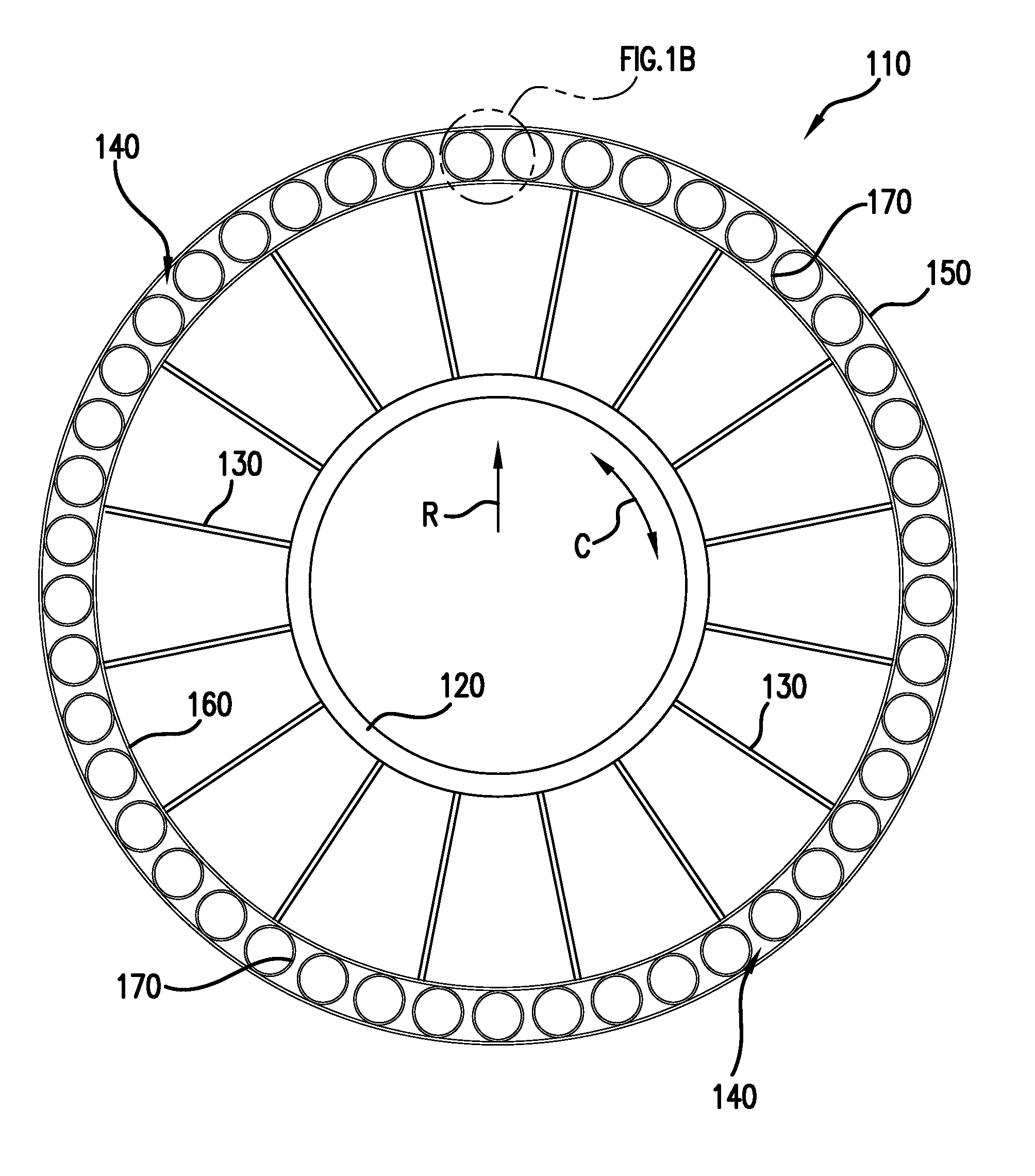
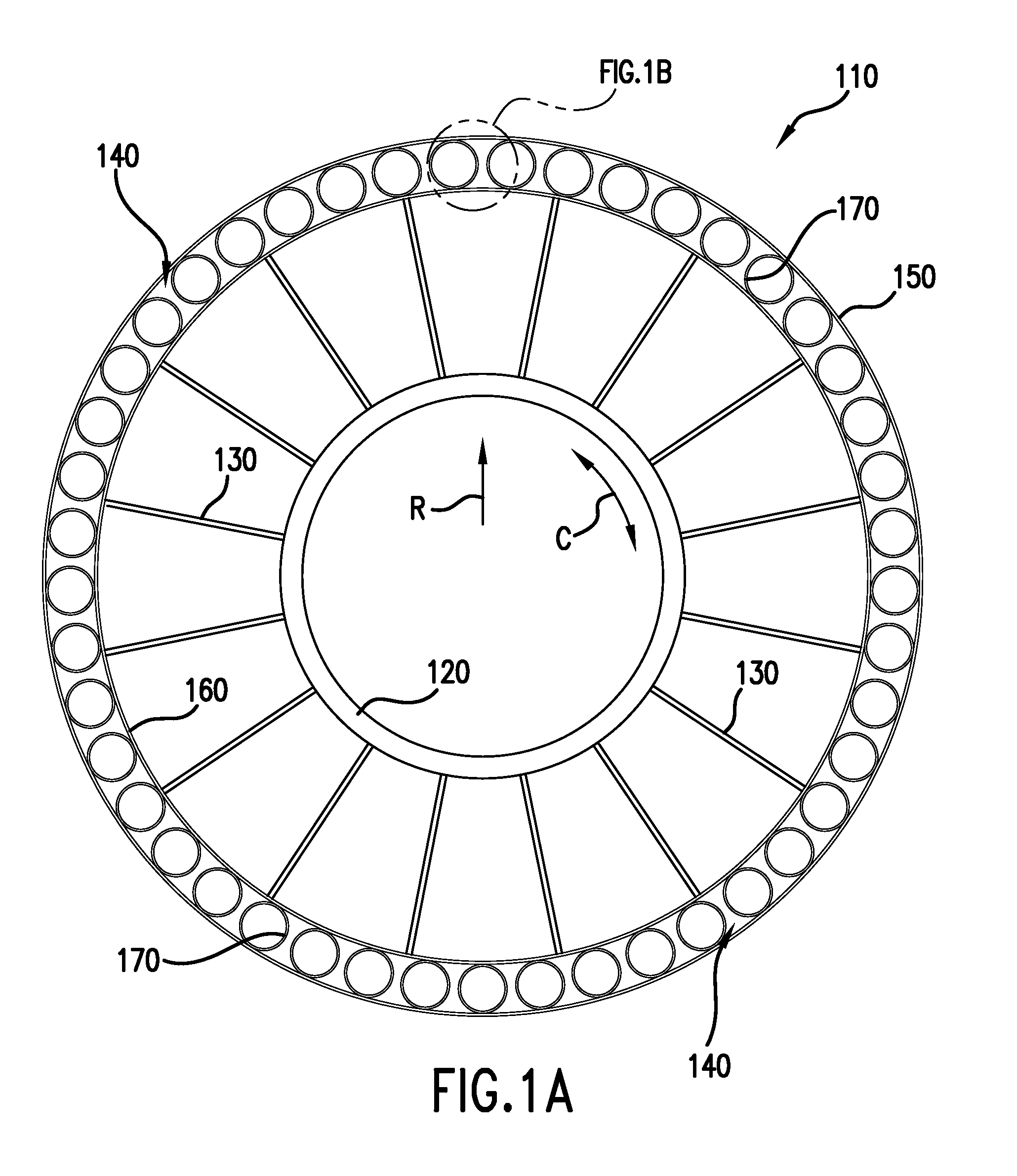
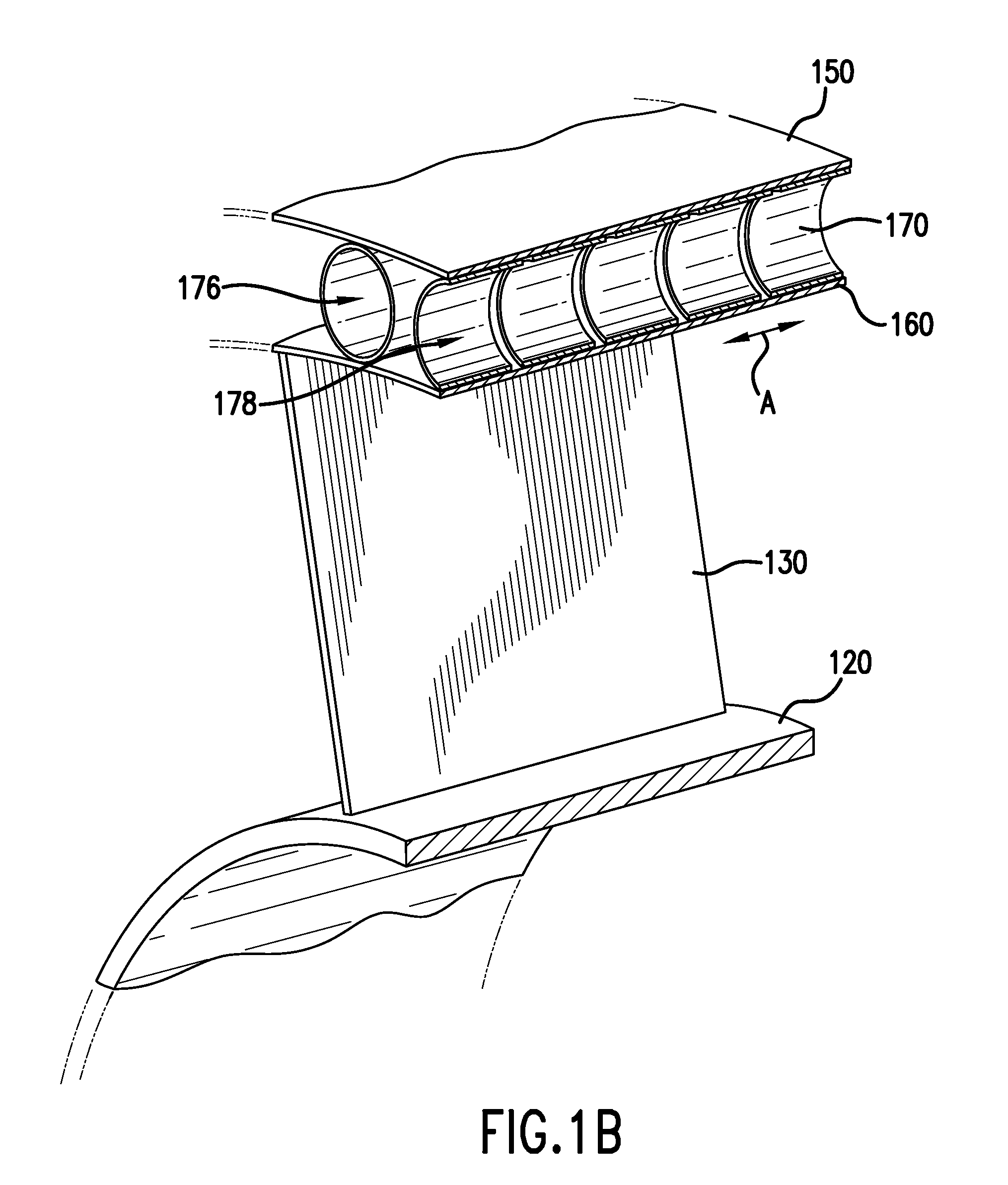
[0015]An exemplary embodiment of a wheel 110 according to the present invention is shown in FIG. 1A with a portion of wheel 110 being shown in FIG. 1B. Wheel 110 defines radial directions R, circumferential directions C (FIG. 1A), and axial directions A (FIG. 1B). Wheel 110 includes a hub 120 connected to a shear band 140 by multiple support elements 130. Shear band 140 includes multiple cylindrical elements 170 that are spaced circumferentially about shear band 140. Hub 120 provides for the connection of wheel 110 to a vehicle and may include a variety of configurations for connection as desired. For example, hub 120 may be p...


PUM

PropertyMeasurementUnit
Efficiencyaaaaaaaaaa
Shapeaaaaaaaaaa

Abstract

A shear band that may be used as part of a structurally supported wheel is provided. More particularly, a shear band constructed from resilient, cylindrical elements attached between inextensible members is described. In certain embodiments, the shear band may be constructed entirely or substantially without elastomeric or polymer-based materials. Multiple embodiments are available including various arrangements of the cylindrical elements between the members as well as differing geometries for the cylindrical elements.

Description

TECHNICAL FIELD OF THE INVENTION[0001]The present invention relates to a shear band that may be used as part of a structurally supported wheel. More particularly, a shear band constructed from resilient, cylindrical elements attached between circumferential members is provided. In certain embodiments, the shear band may be constructed entirely or substantially without elastomeric or polymer-based materials, which allows for application in extreme environments.BACKGROUND OF THE INVENTION[0002]The use of structural elements to provide load support in a tire without the necessity of air pressure has been previously described. For example, U.S. Pat. No. 6,769,465 provides a resilient tire that supports a load without internal air pressure. This tire includes a ground contacting tread portion, a reinforced annular member, and sidewall portions that extend radially inward from the tread portion. By way of further example, U.S. Pat. No. 7,201,194 provides a structurally supported non-pneum...

Claims


Application Information

Patent Timeline
IPC IPC(8): B60C7/00B60B1/00
CPCB60B9/00B60B9/12B60B9/14B60B2360/102B60B2360/141B60B2360/341Y10T152/10387B60B2900/3312B60B2900/551B60C7/16B60C9/18B60Y2200/10B60Y2200/20B60B2360/50
Inventor MCNIER, JARED HAHNNEWMAN, JOSEPH SCOTTREYNOLDS, JOSHUA STUARTSTOWE, DAVID THOMASTAYLOR, ZACHARY JAMESTHOMPSON, RONALD HOBART
Owner MICHELIN RECH & TECH SA
Why Eureka
Try Eureka