Partial image update for electrophoretic displays

an electrophoretic display and image update technology, applied in the field of partial image update of electrophoretic displays, can solve the problems of limiting the capability of the display to a single waveform per image update, and the driving scheme does not allow multiple waveforms during image frame update, so as to reduce the memory required for image upda

Inactive Publication Date: 2010-08-05
E INK CALIFORNIA
View PDF104 Cites 159 Cited by
  • Summary
  • Abstract
  • Description
  • Claims
  • Application Information

AI Technical Summary

Benefits of technology

[0006]The present invention is directed to methods for partial image updates. Such methods provide the display controller the ability to update selected areas of an image that require updating and leave other areas unchanged. The methods also allow for multiple waveforms to be used for specific regions, giving the display the capability of updating each region with its own waveform. The methods of the invention can also reduce the memory required for image updates, especially if only a small percentage of the image is changing. In practice, the methods may be implemented by a uni-polar driving scheme, a bi-polar driving scheme or a combination of both.

Problems solved by technology

The driving schemes also do not allow for multiple waveforms to be used during an image frame update, i.e., each pixel on the image frame uses the same waveform.
This limits the capability of the display to a single waveform per image update.

Method used


Image

  • Partial image update for electrophoretic displays
  • Partial image update for electrophoretic displays
  • Partial image update for electrophoretic displays

Examples


Embodiment Construction

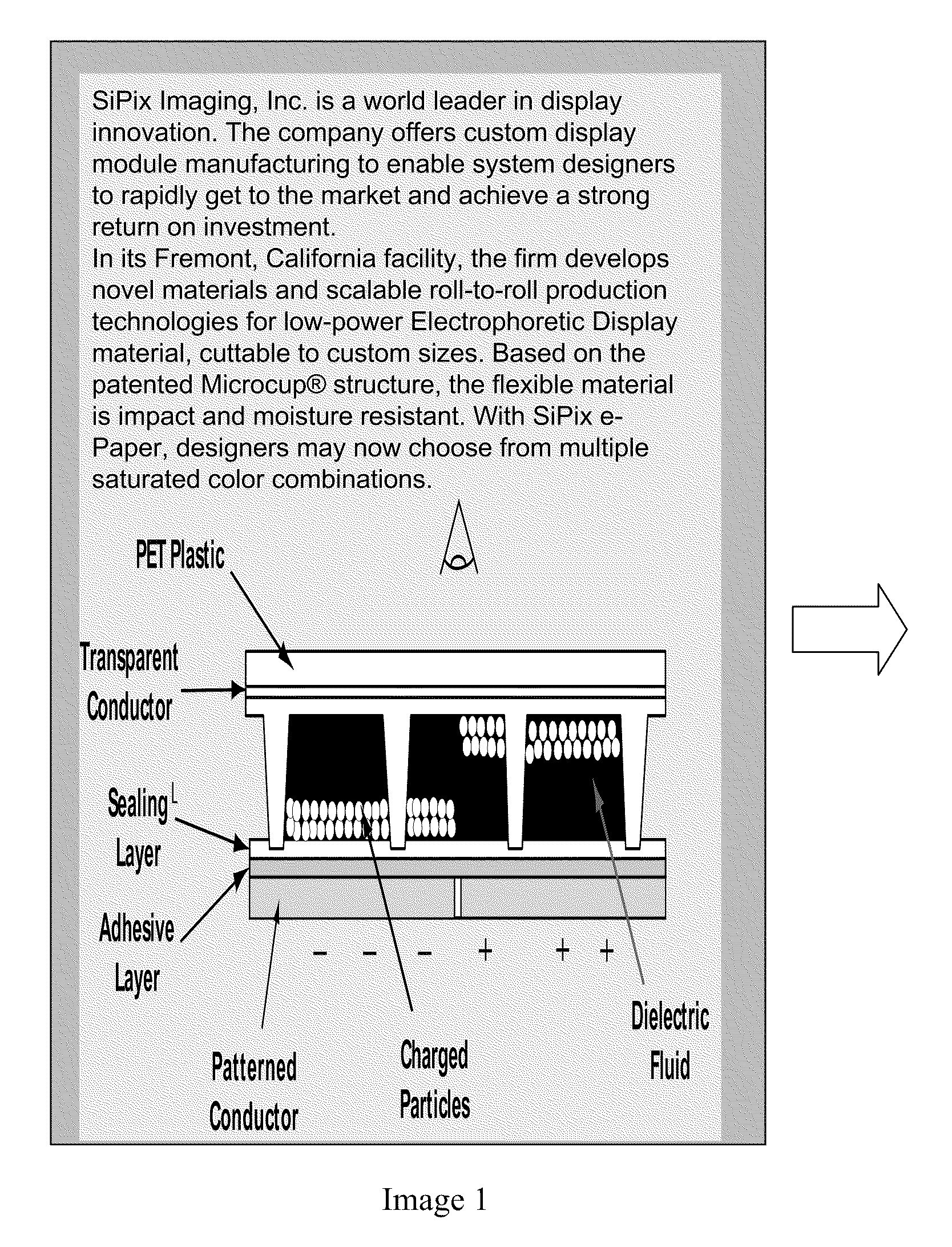
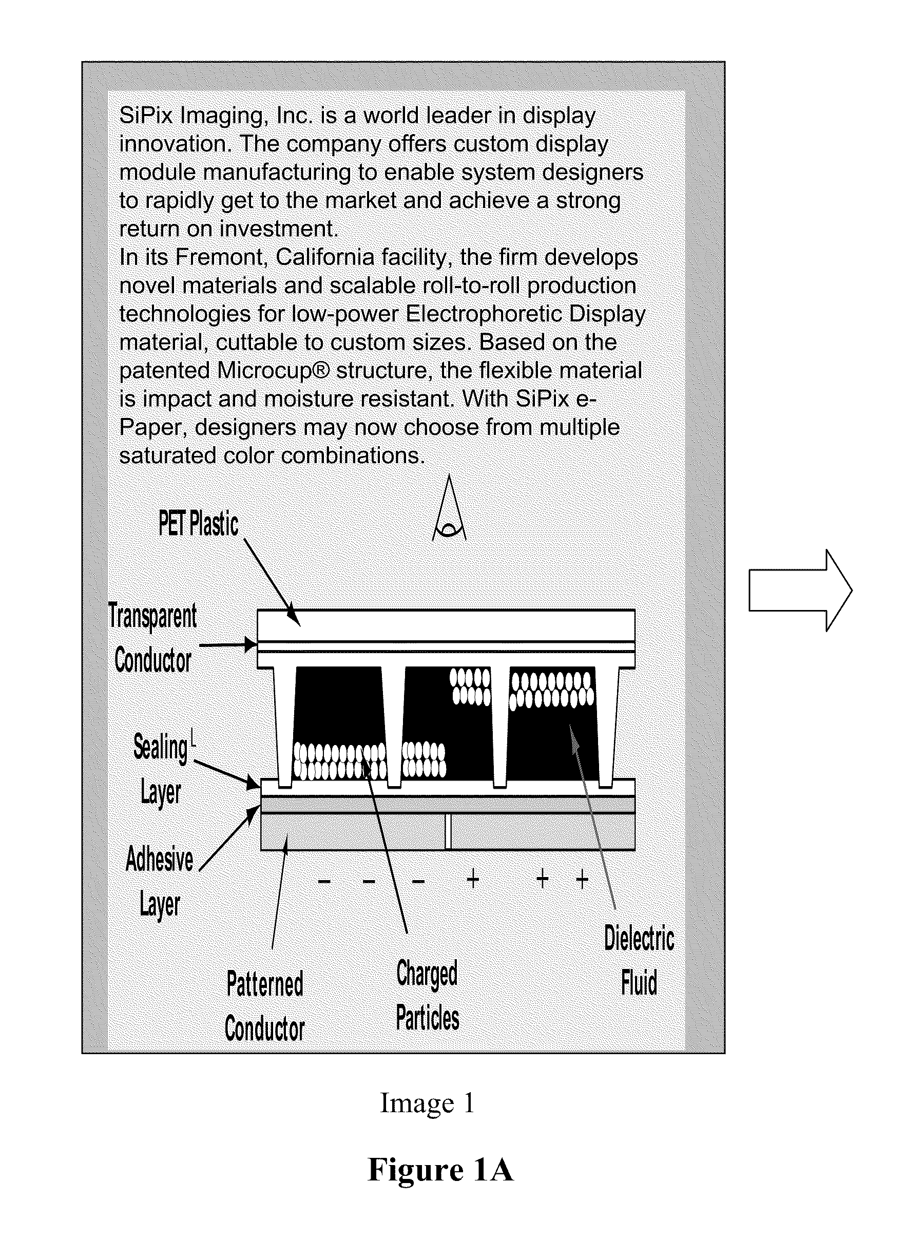
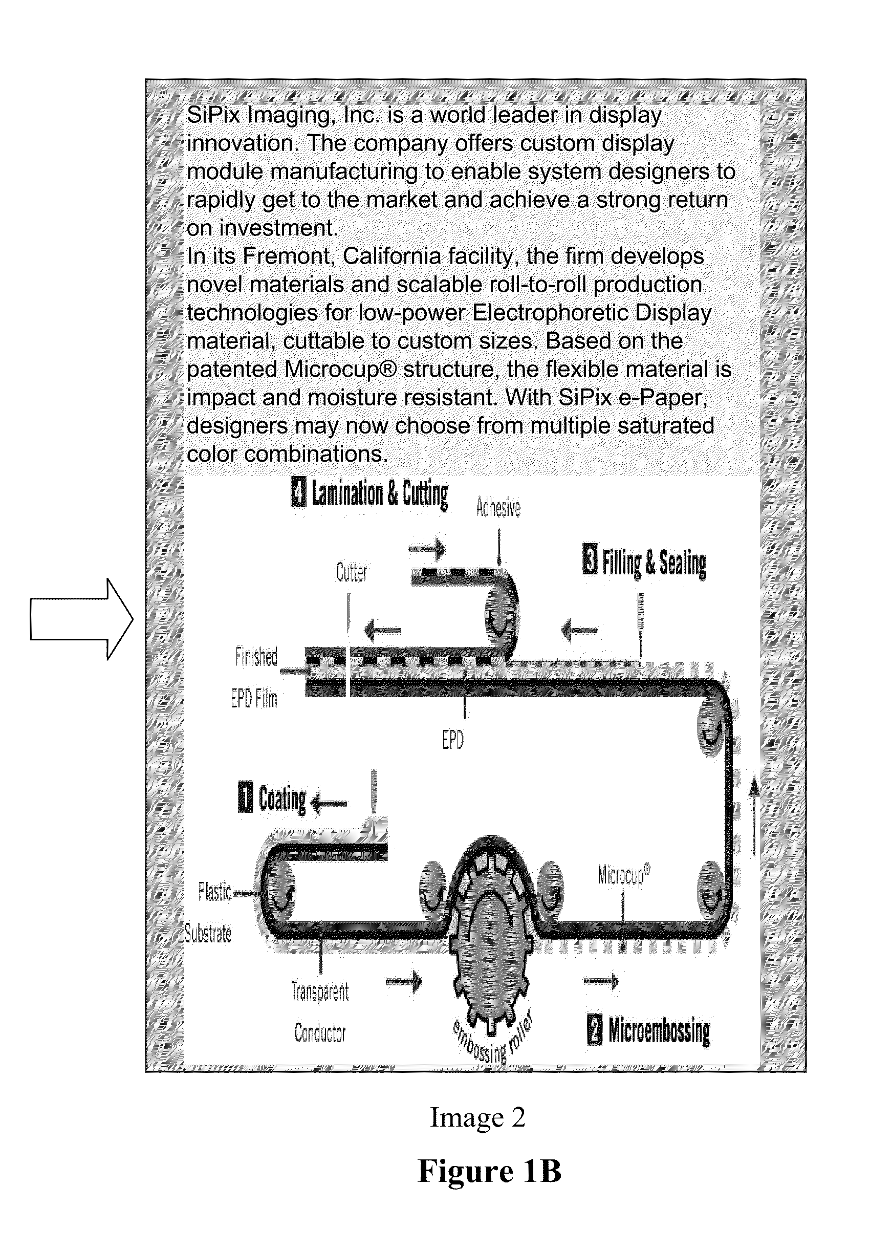
[0032]FIG. 1 illustrates the term “partial image update”. As shown, Image 1 is the original image and Image 2 is an updated image. Between the two images, only the drawing at the bottom of the page has changed while other sections remain unchanged.

[0033]The present invention is directed to methods which would only update the portions of the image that are changing; but not the remaining portions of the image which would remain unchanged.

[0034]In the methods, regions have to be defined first. The regions can be of any size from the entire display screen down to the size of a single pixel. An image may be divided into any number of regions. The regions may also overlap, with a region order of precedence defined. Regions may also be of any shape and in any location on the display screen.

[0035]FIG. 2 is an abbreviated version demonstrating the concept of regions. As shown, a display screen has 11×11 pixels and five defined regions (R0, R1, R2, R3 and R4). The entire screen is defined as...


PUM


Abstract

The present invention is directed to methods for partial image updates. Such methods provide the display controller the ability to update selected areas of an image that require updating and leave other areas unchanged. The methods also allow for multiple waveforms to be used for specific regions, giving the display the capability of updating each region with its own waveform.

Description

[0001]This application claims priority to U.S. Provisional Application No. 61 / 148,735, filed Jan. 30, 2009; the content of which is incorporated herein by reference in its entirety.FIELD OF THE INVENTION[0002]The present invention is directed to methods useful for partial image update of electrophoretic displays.BACKGROUND OF THE INVENTION[0003]An electrophoretic display (EPD) is a non-emissive device based on the electrophoresis phenomenon of charged pigment particles suspended in a solvent. The display usually comprises two plates with electrodes placed opposing each other. One of the electrodes is usually transparent. A suspension composed of a colored solvent and charged pigment particles is enclosed between the two plates. When a voltage difference is imposed between the two electrodes, the pigment particles migrate to one side or the other, according to the polarity of the voltage difference. As a result, either the color of the pigment particles or the color of the solvent ma...

Claims


Application Information

Patent Timeline
Patent Type & Authority Applications(United States)
IPC IPC(8): G09G5/10
CPCG09G3/344G09G2310/04G09G3/3655
Inventor LIN, CRAIGPHAM, TINPERI, MANASAWEI, CHUN-ANCHAN, BRYAN HANSHO, ANDREW
Owner E INK CALIFORNIA
Why Eureka
Try Eureka