Systems and methods for optimizing and maintaining visualization of a surgical field during the use of surgical scopes

a surgical field and visualization technology, applied in the field of surgical scopes, can solve the problems of generating mist, smoke and other debris, inconvenient for the scope operator and the surgeon, and becoming suspended throughout the expanded abdominal space, so as to maintain the visualization of the surgical site and achieve clear visualization

Inactive Publication Date: 2010-08-05
FLOSHIELD INC
View PDF104 Cites 49 Cited by
  • Summary
  • Abstract
  • Description
  • Claims
  • Application Information

AI Technical Summary

Benefits of technology

[0007]One aspect of the invention provides a view optimizing assembly having a deflector assembly with critical physical, pneumatic, and optical characteristics that make possible intra-operative defogging, surgical debris deflection, and cleaning of a laparoscope lens during minimally invasive surgery, while also maintaining visualization of the surgical site. In use, the view optimizing assembly makes possible the practice of a surgical method for maintaining clear visualization of the surgical site without removing the laparoscope 12 from the abdominal cavity for the purpose of cleaning or de-fogging its lens.
[0008]Another aspect of the invention provides a view optimizing assembly having a quick exchange feature. In use, the quick exchange feature makes possible a surgical method for maintaining clear visualization that includes the ability to make a quick exchange of laparoscopes having different operating characteristics (e.g., laparoscopes with different tip angles, lengths, or diameters) entirely on the sterile operating field and without interference with the preexisting surgical set-up on the sterile operating field. The view optimizing assembly integrates with the existing suite of minimally invasive instrumentation. It does not interfere with the surgical set-up, and it requires minimal change in the process or practice of a surgical operating room (OR) team.

Problems solved by technology

The local environment within a patient's abdominal space is generally rather warm and humid, and the use of devices such as harmonic scalpels and other cutting and coagulating devices generate mist, smoke, and other debris that is released into the surgical field and often becomes suspended throughout the expanded abdominal space.
The need to remove the scope to defog and remove debris from the lens is inconvenient for the scope operator and the surgeon and can interrupt and undesirably prolong surgical procedures.

Method used


Image

  • Systems and methods for optimizing and maintaining visualization of a surgical field during the use of surgical scopes
  • Systems and methods for optimizing and maintaining visualization of a surgical field during the use of surgical scopes
  • Systems and methods for optimizing and maintaining visualization of a surgical field during the use of surgical scopes

Examples


Embodiment Construction

[0021]Although the disclosure hereof is detailed and exact to enable those skilled in the art to practice the invention, the physical embodiments herein disclosed merely exemplify the invention, which may be embodied in other specific structure. While the preferred embodiment has been described, the details may be changed without departing from the invention, which is defined by the claims.

I. View Optimizing Assembly

[0022]A. Overview

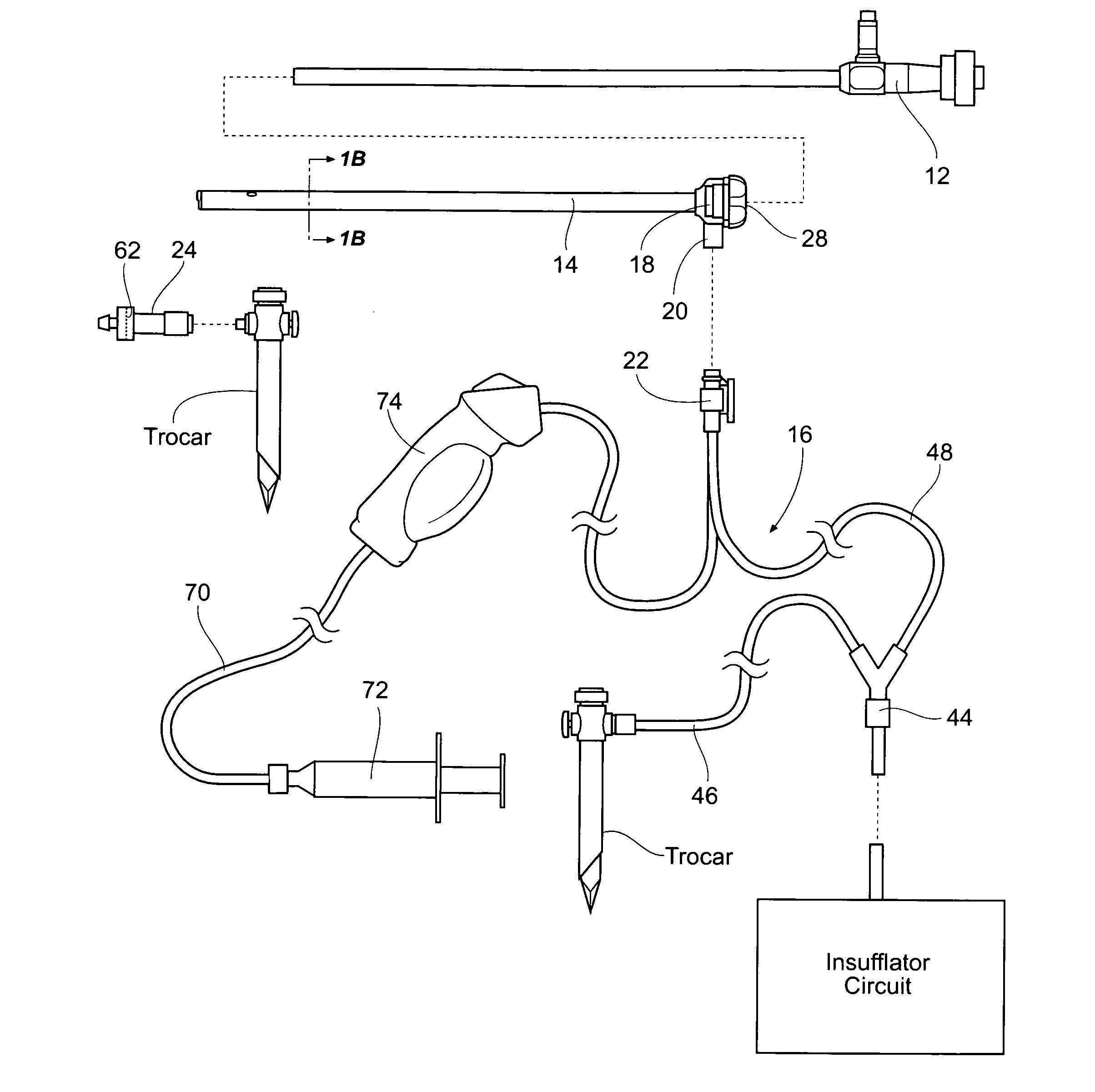
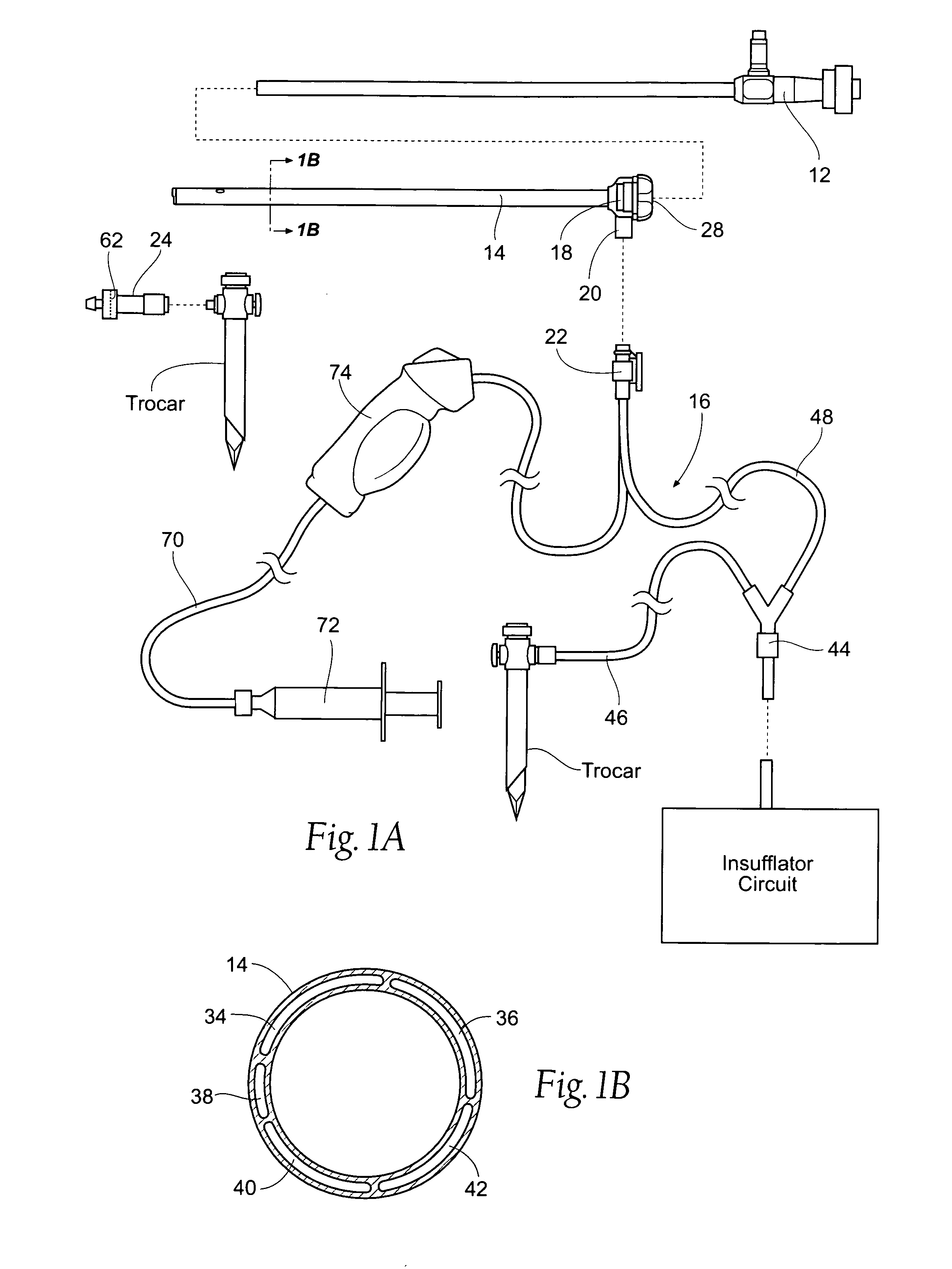
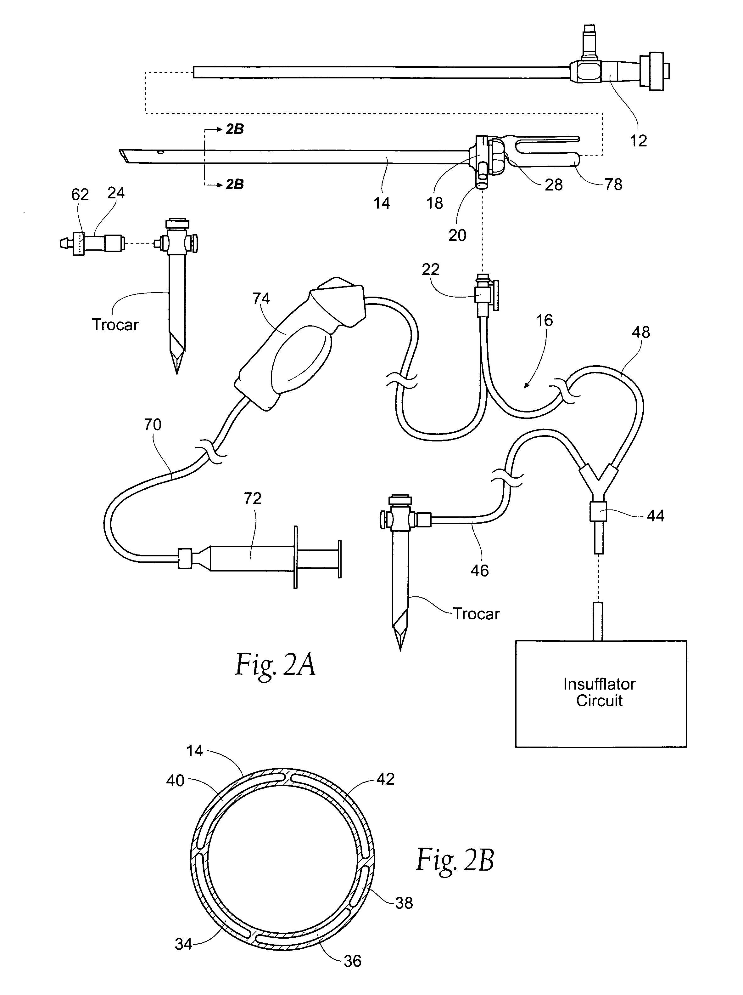
[0023]FIGS. 1A / 1B and FIG. 2A / 2B show a view optimizing assembly 10 for use in association with a state of the art laparoscope 12. In FIGS. 1A / 1B, the laparoscope 12 possesses at 0° (blunt) shaft tip In FIGS. 2A / 2B, the laparoscope possess an angle shaft tip (e.g., a 30° shaft tip or 45° shaft tip). The components of the view optimizing assembly 10 may be made from plastic materials (extruded and / or molded), but other suitable materials, such as metal or a composite material, or combinations thereof could be used.

[0024]As will be described in greater det...


PUM


Abstract

Systems and methods make use of a view optimizing assembly having a deflector assembly with critical physical, pneumatic, and optical characteristics that make possible intra-operative defogging, surgical debris deflection, and cleaning of a laparoscope lens during minimally invasive surgery, while also maintaining visualization of the surgical site. The view optimizing assembly can incorporate a quick exchange feature, which makes possible a surgical method for maintaining clear visualization that includes the ability to make a quick exchange of laparoscopes having different operating characteristics (e.g., laparoscopes with different tip angles, lengths, or diameters) entirely on the sterile operating field and without interference with the preexisting surgical set-up on the sterile operating field. The view optimizing assembly integrates with the existing suite of minimally invasive instrumentation. It does not interfere with the surgical set-up, and it requires minimal change in the process or practice of a surgical operating room (OR) team.

Description

RELATED APPLICATION[0001]This application claims the benefit of U.S. Provisional Patent Application Ser. No. 61 / 121,514 filed 10 Dec. 2008, and entitled “Device for Maintaining Visualization with Surgical Scopes,” which is incorporated herein by reference. This application also claims the benefit of U.S. Provisional Patent Application Ser. No. 61 / 170,864 filed 20 Apr. 2009, and entitled “Surgical Scope Stabilizer for Use with Device for Maintaining Visualization with Surgical Scopes” which is also incorporated herein by reference. This application is also a continuation-in-part of U.S. Utility application Ser. No. 11 / 765,340, filed 19 Jun. 2007, which corresponds to PCT Application Serial No. PCT / US2008 / 067426, filed 19 Jun. 2008, the entirety of which applications are incorporated herein by reference.FIELD OF THE INVENTION[0002]The invention generally relates to surgical scopes, and, more particularly, for optimizing and maintaining visualization of a surgical field when using a su...

Claims


Application Information

Patent Timeline
Patent Type & Authority Applications(United States)
IPC IPC(8): A61B1/12
CPCA61B1/00135A61M2205/3344A61M13/003A61B1/3132A61B17/3474A61B1/127A61B2017/347A61B1/00091A61B1/126A61M2202/0225A61B1/00142A61B1/015A61B1/313
Inventor POLL, WAYNE L.HUDDLESTON, MATTHEW J.CRISAFULLI, CAROLINE M.LANDIS, ADAMDRACH, GREGORY P.
Owner FLOSHIELD INC
Why Eureka
Try Eureka