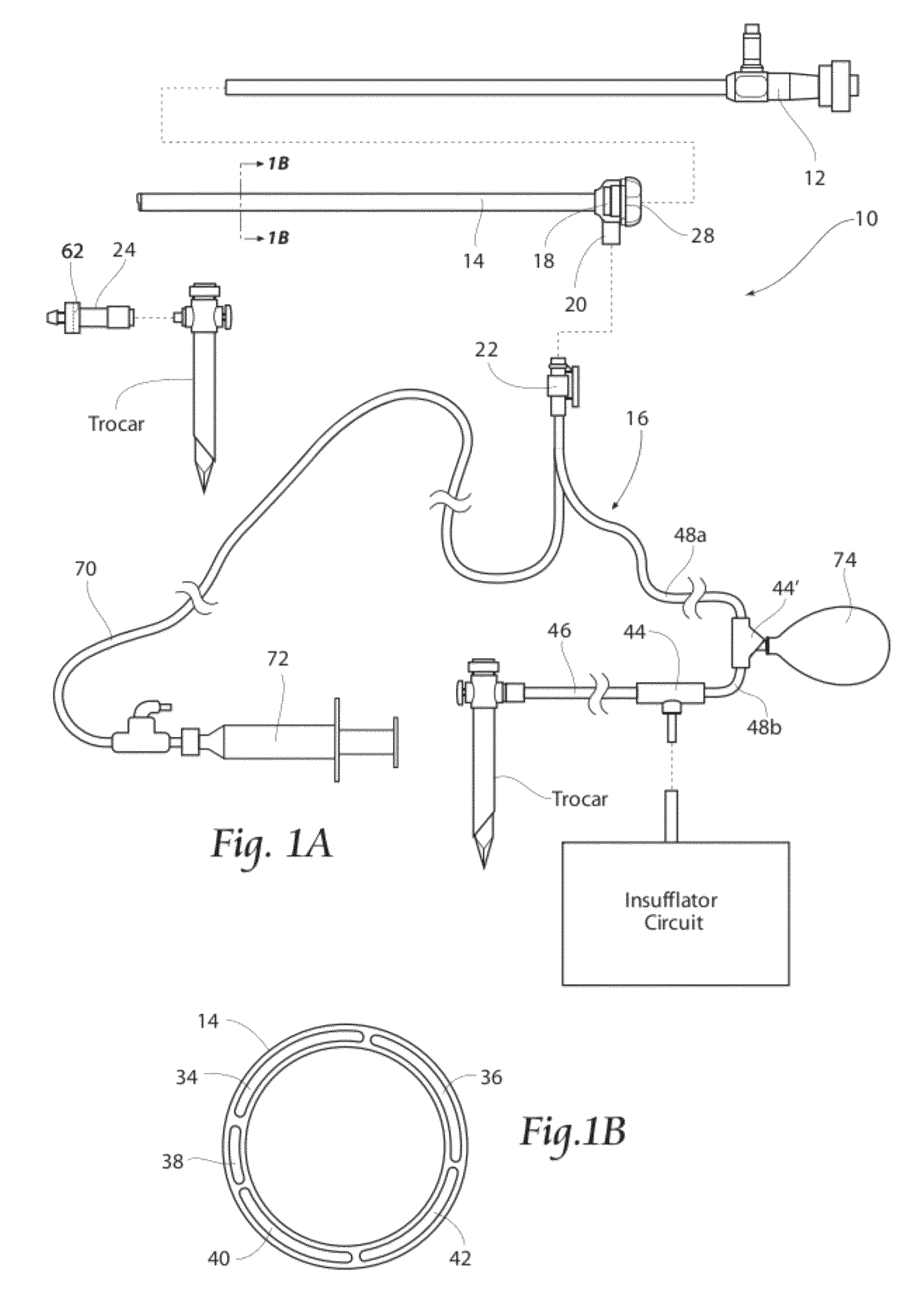
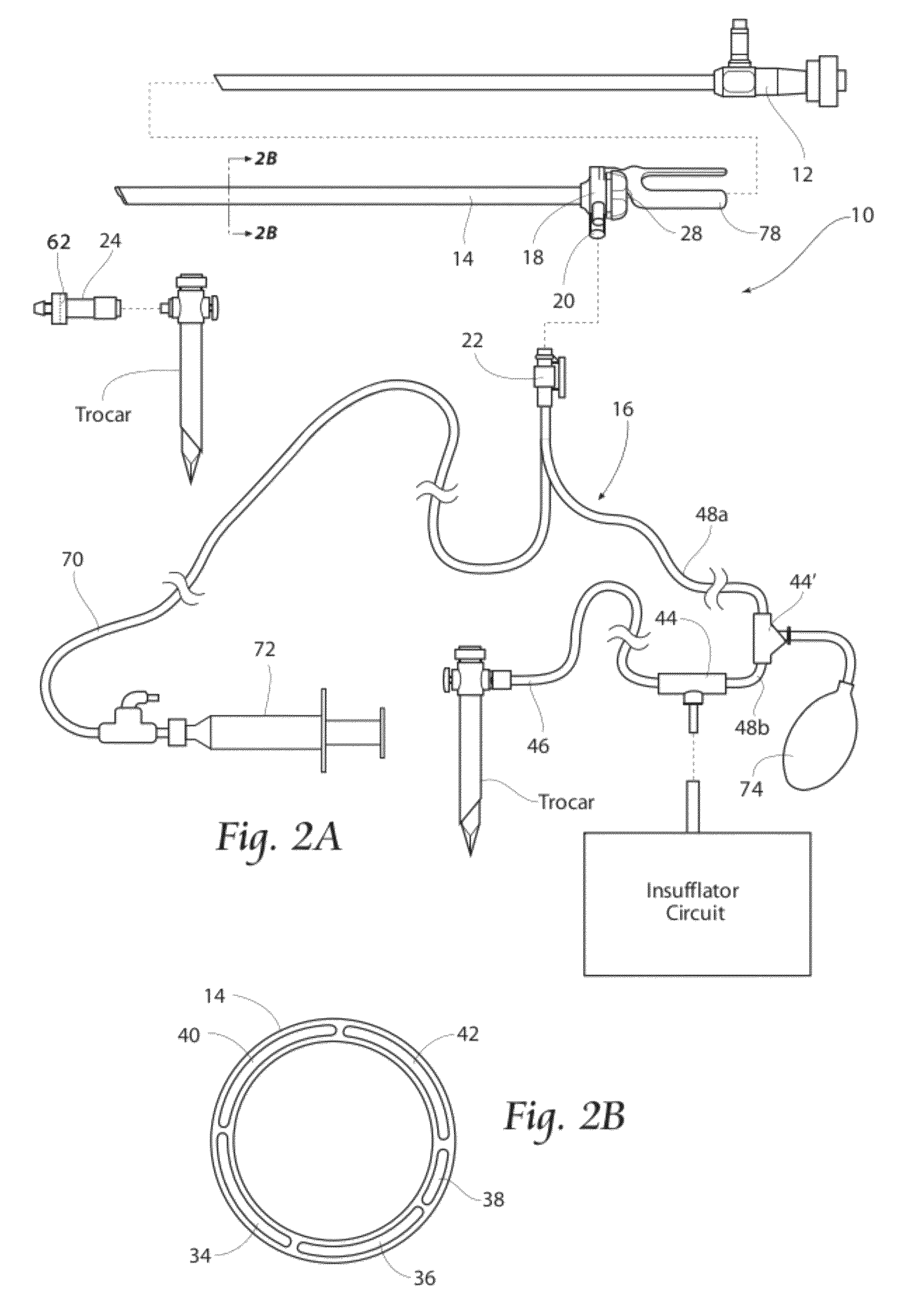
Systems and methods for optimizing and maintaining visualization of a surgical field during the use of surgical scopes
a surgical field and visualization technology, applied in the field of surgical scopes, can solve the problems of generating mist, smoke and other debris, inconvenient for the scope operator and the surgeon, and becoming suspended throughout the expanded abdominal space, and achieve the effect of maintaining visualization of the surgical si
- Summary
- Abstract
- Description
- Claims
- Application Information
AI Technical Summary
Benefits of technology
Problems solved by technology
Method used
Image
Examples
example 1
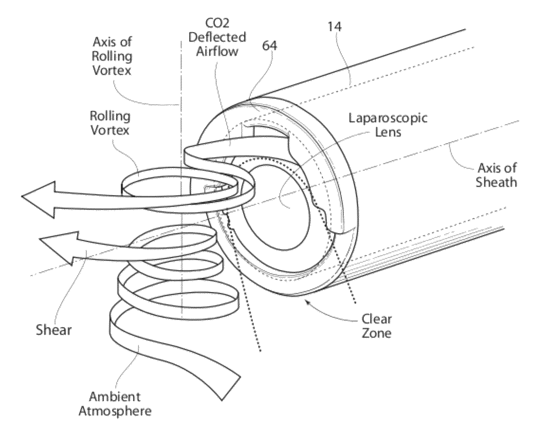
[0137]A plume of water vapor (mist) is created by an ultrasonic transducer and channel through a tube. The distal end of sheath 14 (with a deflection assembly 64) is positioned over the plume, and CO2 is conveyed through the deflection assembly 64 in the manner described. FIG. 25B is a photograph demonstrating the presence of a “vortex shearing” effect across and beyond the laparoscopic lens for a deflection assembly 64 on a blunt sheath 14. FIG. 26B is a photograph demonstrating the presence of a “vortex shearing” effect across and beyond the laparoscopic lens for a deflection assembly 64 on a 30° angled sheath 14. In both instances, the deflected airflow is shown, with the accompanying shear and the resulting clear zone across and beyond the laparoscopic lens.
[0138]The rolling vortex for a blunt end sheath 14 is depicted in FIG. 25A (with a corresponding photograph shown in FIG. 25B), and the rolling vortex for an angled sheath is depicted in FIG. 28A (with a corresponding photogr...
example 2
[0182]Various sheaths (identified as Devices 1 to 7) were constructed with distal plenums having differing sizes and configurations. These are described in the following Table 1:
[0183]
TABLE 1Sheaths ConstructedProximalDevicePlenumProximal TrimDesignationsConfigurationDistances1As Shown in FIG.All lumens 0.14037Binch2As Shown in FIG.Lumens 1 and 4 =38A0.140 inchLumens 2 and 3 =0.70 inch3As Shown in FIG.All Lumens 0.33038Binch4As Shown in FIG.Lumens 1, 2, and 4 =38C0.140 inchLumen 3 = 0.705As Shown in FIG.Lumens 1 and 2 =38D0.140 inchLumens 3 and 4 = 0.0inch6As shown in FIG.Lumens 1 and 4 =39A0.140 inchLumens 2 and 3 =0.70 inchDivider Between 1and 2 at 0.140 inch7As Shown in FIG.All Lumens 0.14040AinchDivider Between 2and 3 at 0.140 inch
[0184]Pressurized CO2 was conveyed into the plenum of each Device 1 to 7, at an entrance pressure of 15 mmHg and a flow rate of 14 L / min. Air speeds (m / sec) were measured coming out of each individual lumen (with no defection assembly attached at the d...
PUM
 Abstract
Description
Claims
Application Information
 - R&D
- Intellectual Property
- Life Sciences
- Materials
- Tech Scout
- Unparalleled Data Quality
- Higher Quality Content
- 60% Fewer Hallucinations
Browse by: Latest US Patents, China's latest patents, Technical Efficacy Thesaurus, Application Domain, Technology Topic, Popular Technical Reports.
© 2025 PatSnap. All rights reserved.Legal|Privacy policy|Modern Slavery Act Transparency Statement|Sitemap|About US| Contact US: help@patsnap.com


