Valve timing adjusting apparatus

a timing adjustment and valve technology, applied in the direction of valve arrangement, yielding coupling, coupling, etc., can solve the problem of deteriorating the accuracy of adjusting the rotational phas

Active Publication Date: 2010-08-12
DENSO CORP
View PDF5 Cites 37 Cited by
  • Summary
  • Abstract
  • Description
  • Claims
  • Application Information

AI Technical Summary

Problems solved by technology

The above hysteresis may deteriorate the accuracy in adjusting the rotational phase or the valve timing by using working fluid, and thereby needs to be improved.

Method used


Image

  • Valve timing adjusting apparatus
  • Valve timing adjusting apparatus
  • Valve timing adjusting apparatus

Examples


first embodiment

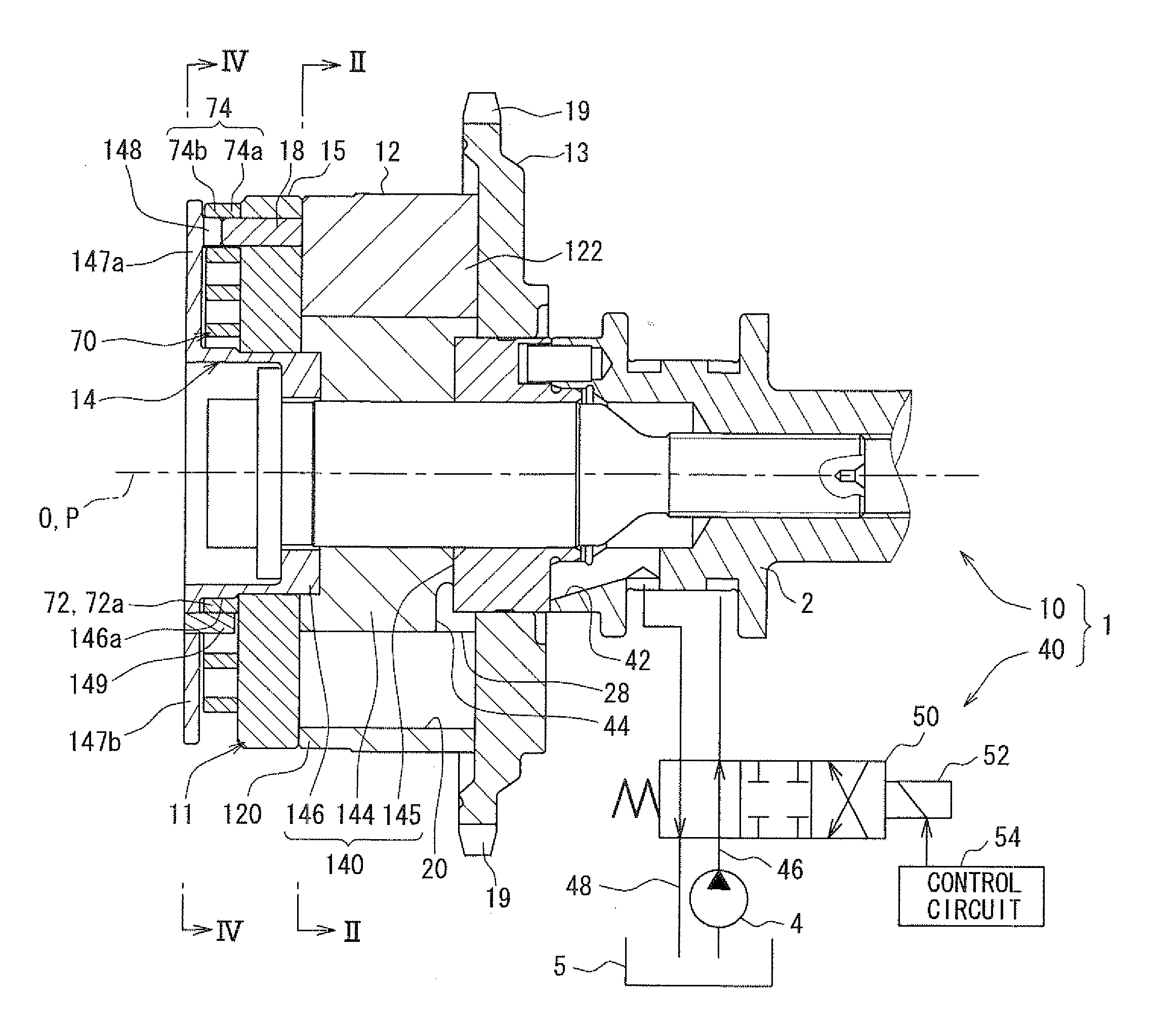
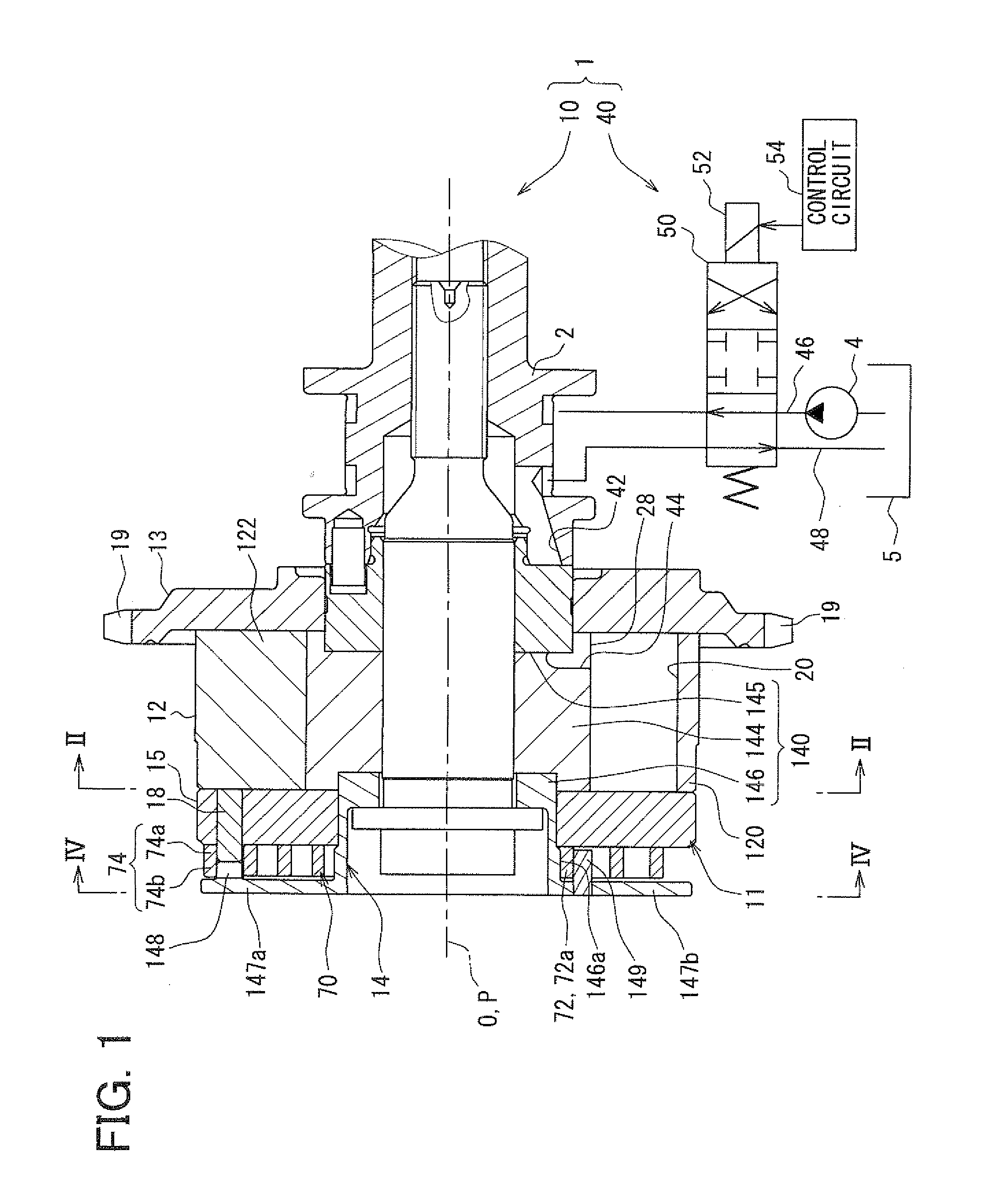
[0032]FIG. 1 shows an example, in which a valve timing adjusting apparatus 1 according to the first embodiment of the present invention is applied to an internal combustion engine of a vehicle. The valve timing adjusting apparatus 1 adjusts valve timing of an intake valve by using hydraulic oil that serves as “working fluid”. The intake valve serves as a “valve” that is opened and closed by a camshaft 2 of the engine. The valve timing adjusting apparatus 1 is mounted on a transmission system that transmits engine torque from a crankshaft (not shown) of the engine to the camshaft 2. The valve timing adjusting apparatus 1 includes a drive unit 10 and a control unit 40. The drive unit 10 is driven by hydraulic oil, and the control unit 40 controls supply of hydraulic oil.

(Drive Unit)

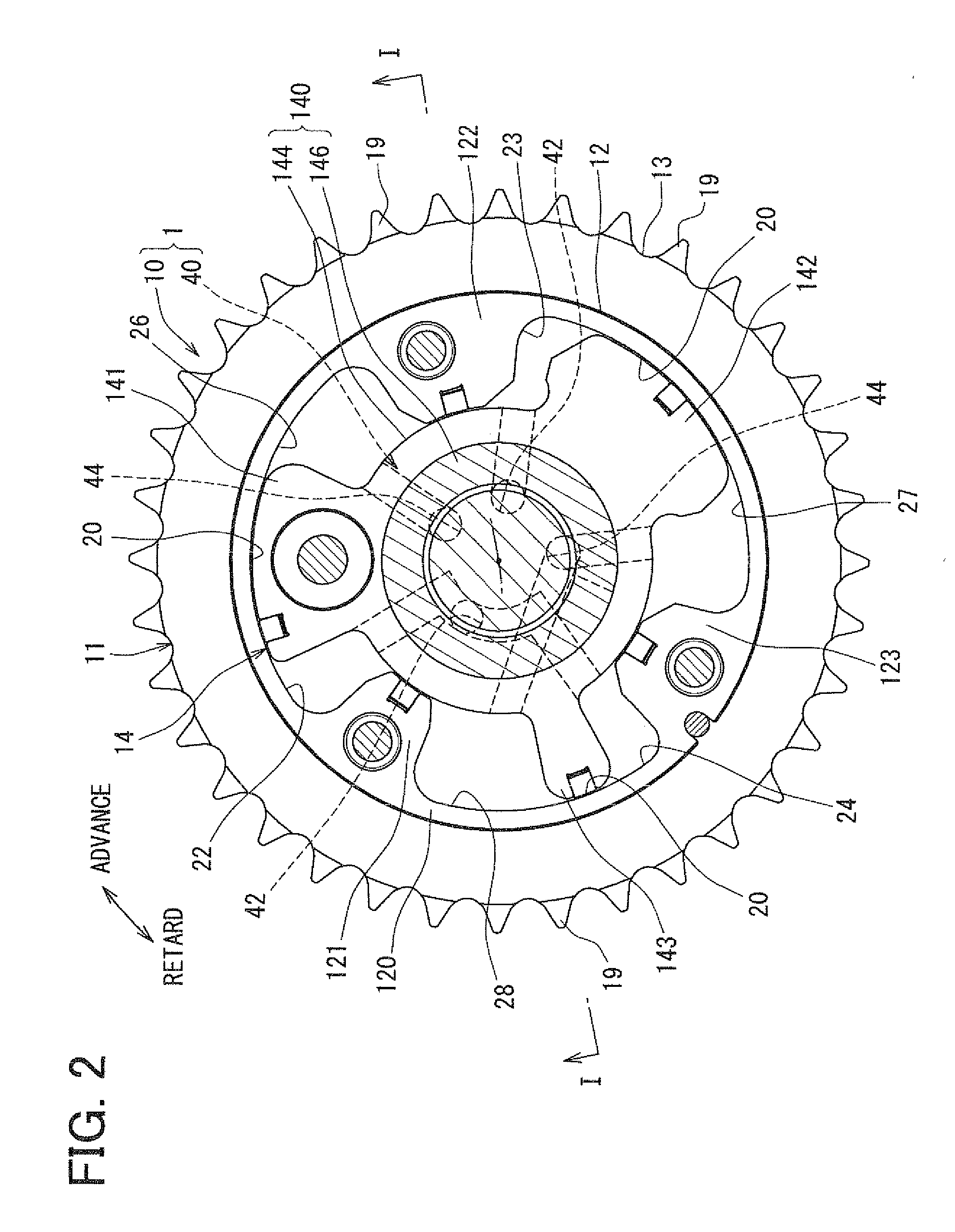
[0033]Firstly, the drive unit 10 will be detailed. The drive unit 10 shown in FIG. 1 and FIG. 2 has a housing 11 that includes a shoe housing 12, a sprocket 13, and a front plate 15.

[0034]The shoe housing 1...

second embodiment

[0062]As shown in FIG. 11, the second embodiment of the present invention is a modification of the first embodiment. A first stopper 1018 of a housing 1011 of the second embodiment is provided at a position radially outward of the second stopper 148 of the vane rotor 14 of the first embodiment. In other words, the first stopper 1018 is off the rotation center O of the rotational shaft 140 by a distance Is that is greater than the preset distance Ls, by which the second stopper 148 is off the rotation center O.

[0063]Furthermore, in the second embodiment, a spiral spring 1070 is also made of the hairspring. The spiral spring 1070 has a most radially outward part 1074 that is curved into an ω-shape such that first and second engagement parts 1074a, 1074b are formed. The first engagement part 1074a is formed at a position that is off the rotation center O of the rotational shaft 140 by a distance that is substantially similar to the distance is, by which the first stopper 1018 is off th...


PUM


Abstract

A valve timing adjusting apparatus includes a housing, a vane rotor, and a spiral spring. The spiral spring has a most radially inward part engaged with a rotational shaft of the vane rotor in a state, where the most radially inward part is wound around the rotational shaft. The rotational phase has an intermediate position defined between a full retard position and a full advance position of the rotational phase. The spiral spring has a radially outward segment that is located radially outward of the most radially inward part. When the rotational phase is in a range on a retard side of the intermediate position or on an advance side of the intermediate position, the radially outward segment is engaged with the stopper such that the spiral spring urges the vane rotor in the advance direction or in the retard direction relative to the housing, respectively.

Description

CROSS REFERENCE TO RELATED APPLICATION[0001]This application is based on and incorporates herein by reference Japanese Patent Application No. 2009-27650 filed on Feb. 9, 2009.BACKGROUND OF THE INVENTION[0002]1. Field of the Invention[0003]The present invention relates to a valve timing adjusting apparatus for an internal combustion engine, wherein the valve timing adjusting apparatus adjusts valve timing of a valve that is opened and closed by a camshaft based on torque transmitted from a crankshaft.[0004]2. Description of Related Art[0005]Conventionally, a valve timing adjusting apparatus, which has a housing and a vane rotor, has been widely used. For example, the housing of the conventional valve timing adjusting apparatus is synchronously rotated with a crankshaft, and the vane rotor is synchronously rotated with a camshaft. In the above valve timing adjusting apparatus, vanes of the vane rotor divides the internal space of the housing into retard chambers and advance chambers t...

Claims


Application Information

Patent Timeline
Patent Type & Authority Applications(United States)
IPC IPC(8): F01L1/34
CPCF01L1/3442F01L2001/34483F01L2001/34453
Inventor FUJIYOSHI, TOSHIKI
Owner DENSO CORP
Why Eureka
Try Eureka