

Multi-rate multi-receiver multi-response aggregation
- Summary
- Abstract
- Description
- Claims
- Application Information
AI Technical Summary
Benefits of technology
Problems solved by technology
Method used
Image

Examples
Embodiment Construction
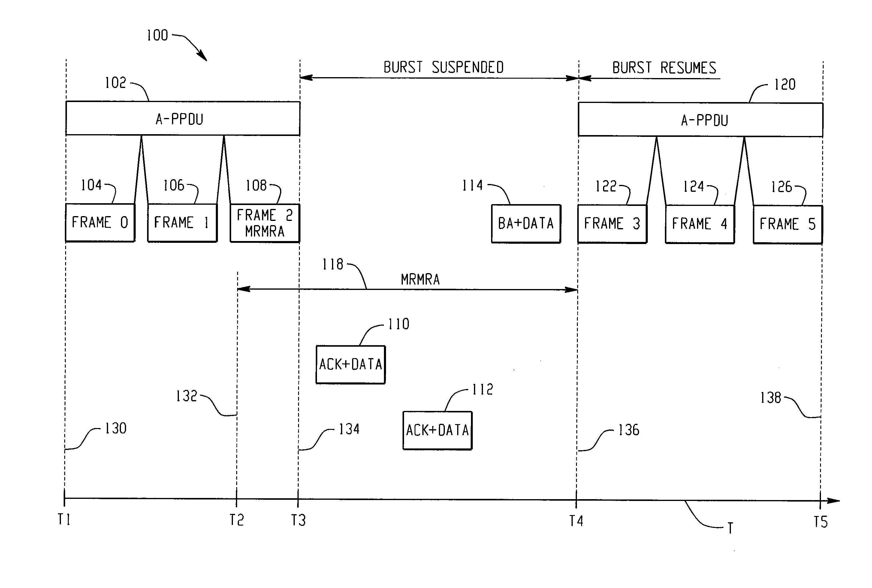
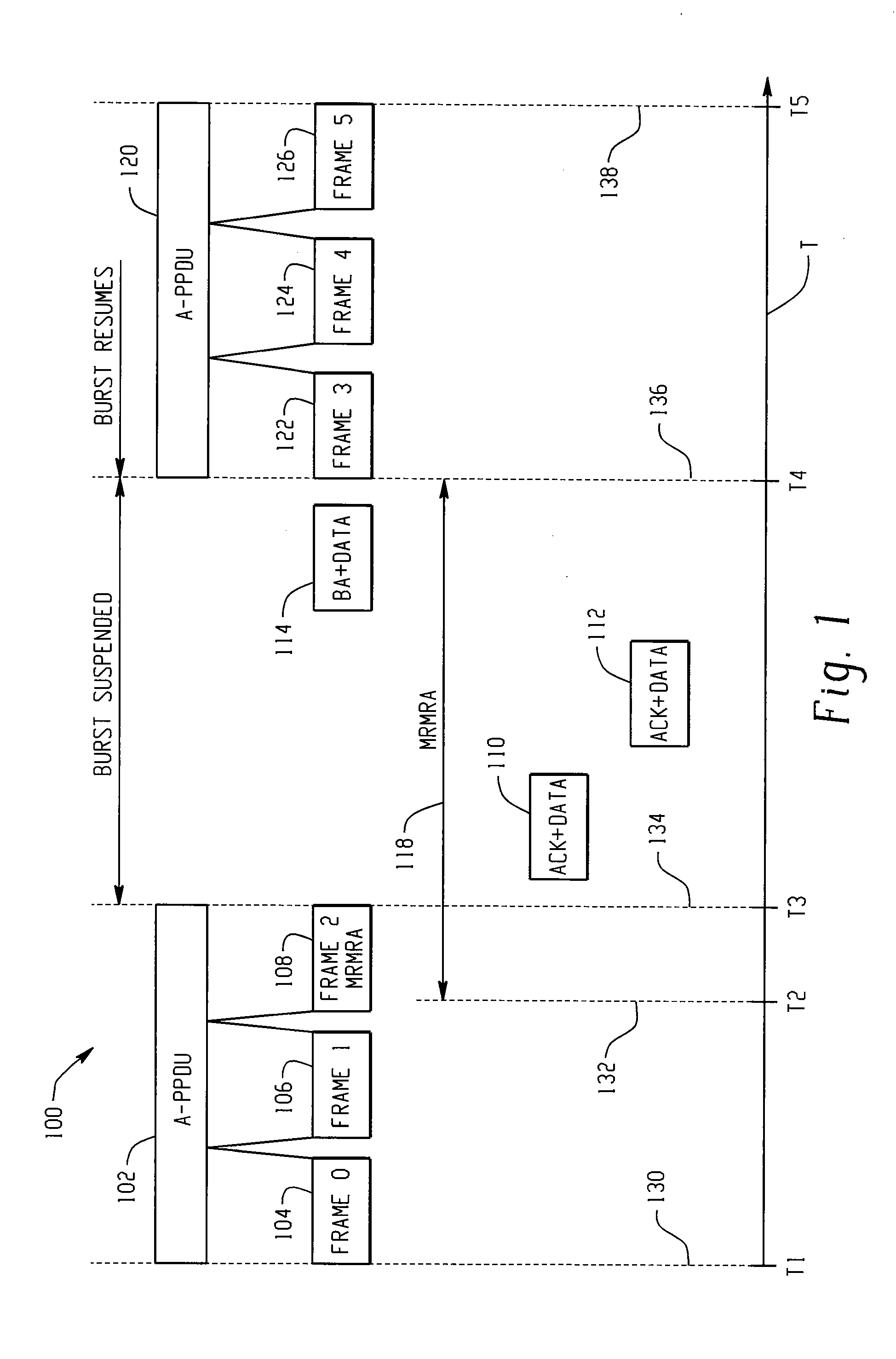
[0023]Throughout this description, the preferred embodiment and examples shown should be considered as exemplars, rather than limitations, of the present invention. The present invention is directed to a multi-rate aggregation scheme that is in the form of PSDU bursting, which aggregates multiple frames, either to the same receiver or a number of receivers of the same rate, in a single PSDU and bursts a number of PSDUs of various rates in sequence. To allow for a MRMRA, the PSDU bursting suspends temporarily after it transmits a MRMRA. After receiving acknowledgements from the recipients of the MRMRA, a block acknowledgement, is transmitted and the bursting resumes. This approach seamlessly combines MRMRA and multi-rate aggregation without introducing any degradation in channel utilization.
[0024]Referring to FIG. 1, there is illustrated an example timing diagram 100 illustrating an aspect of the present invention. A timeline T is employed for the purpose of illustrating the various ...
PUM
 Abstract
Description
Claims
Application Information