
Self-Stabilizing Distributed Symmetric-Fault Tolerant Synchronization Protocol

Inactive Publication Date: 2016-10-27
NASA
View PDF1 Cites 7 Cited by
  • Summary
  • Abstract
  • Description
  • Claims
  • Application Information

AI Technical Summary

Benefits of technology

The patent text describes a synchronization protocol that can quickly and easily synchronize devices with each other. This protocol allows for a fast recovery time and minimizes the impact on the network.

Problems solved by technology

Since physical oscillators are inherently imperfect, local clocks of nodes of a distributed system, driven by these physical oscillators, do not keep perfect time and can drift with respect to real time and with respect to one another.
Prior solutions for synchronization systems have not resolved the need for an approach to perform the above functions with precision, accuracy, efficiency, or that has cross-applicability to many various system architectures.

Method used


Image

  • Self-Stabilizing Distributed Symmetric-Fault Tolerant Synchronization Protocol
  • Self-Stabilizing Distributed Symmetric-Fault Tolerant Synchronization Protocol
  • Self-Stabilizing Distributed Symmetric-Fault Tolerant Synchronization Protocol

Examples


Embodiment Construction

[0020]For purposes of description herein, the terms “upper,”“lower,”“right,”“left,”“rear,”“front,”“vertical,”“horizontal,” and derivatives thereof shall relate to the invention as oriented in FIG. 1. However, it is to be understood that the invention may assume various alternative orientations and step sequences, except where expressly specified to the contrary. It is also to be understood that the specific devices and processes illustrated in the attached drawings, and described in the following specification, are simply exemplary embodiments of the inventive concepts defined in the appended claims. Hence, specific dimensions and other physical characteristics relating to the embodiments disclosed herein are not to be considered as limiting, unless the claims expressly state otherwise.

[0021]In the following description of various examples of the invention, reference is made to the accompanying drawings which show, by way of illustration, various example systems and environments in ...


PUM


Abstract

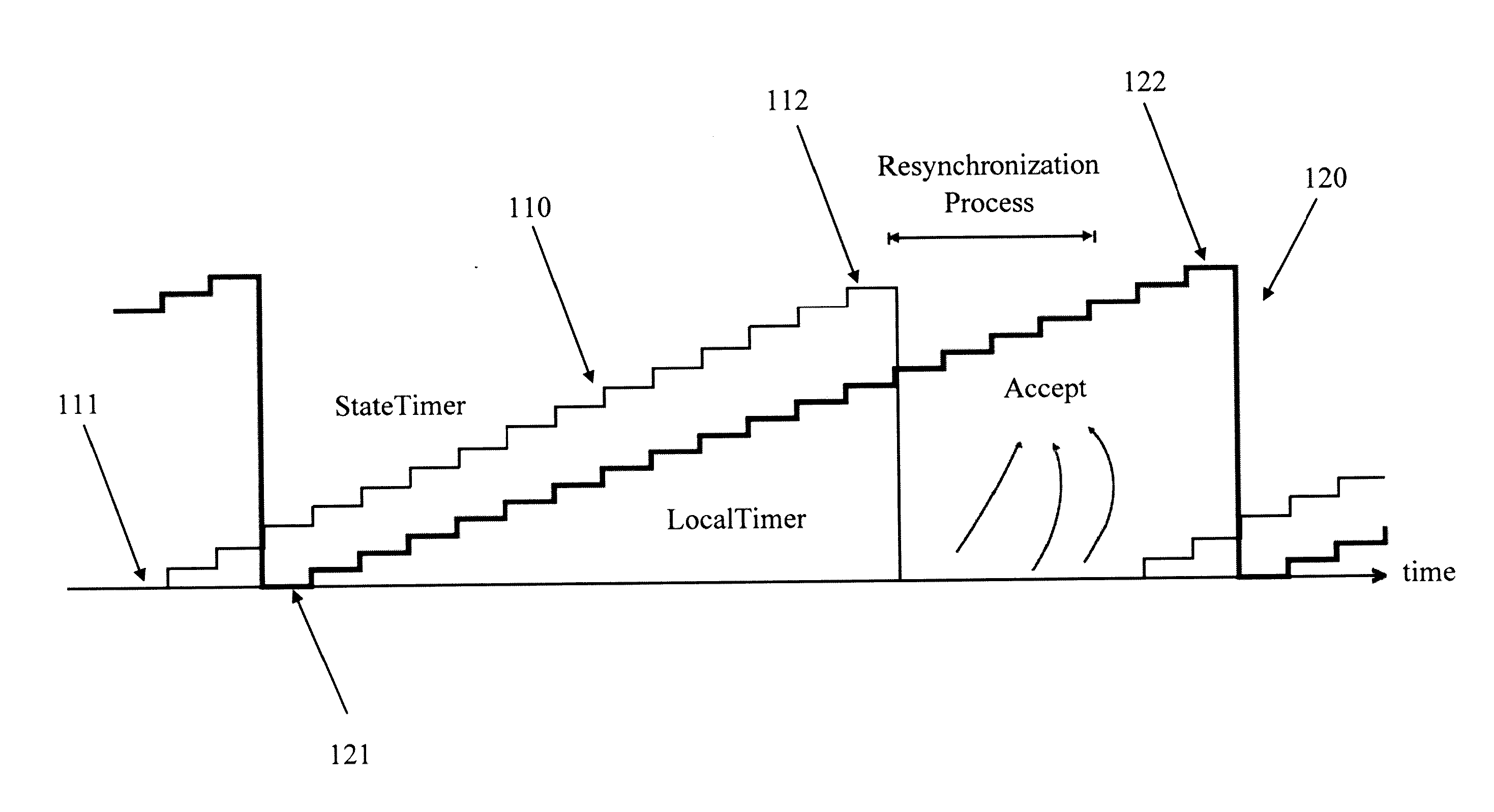
A network system includes at least one node configured to exchange messages through a set of communication links. Each node includes a synchronizer, a set of monitors in communication with the synchronizer, a physical oscillator and a state timer clock and a local timer clock, each clock being driven by the physical oscillator and having a variable clock value that locally tracks passage of clock time for the node. The network system is configured to execute a synchronization process when a specified condition occurs. Upon receiving a Sync message, each of the nodes is configured to store an incoming Sync message, increment a local timer clock value, or ignore the Sync message based on a local timer clock value associated with an incoming Sync message.

Description

CROSS-REFERENCE TO RELATED PATENT APPLICATION(S)[0001]This patent application claims the benefit of and priority to U.S. Provisional Patent Application Number 62 / 150,322, filed on Apr. 21, 2015, the contents of which are hereby incorporated by reference in their entirety.STATEMENT REGARDING FEDERALLY SPONSORED RESEARCH OR DEVELOPMENT[0002]The invention described herein was made by an employee of the United States Government and may be manufactured and used by or for the Government of the United States of America for governmental purposes without the payment of any royalties thereon or therefore.BACKGROUND OF THE INVENTION[0003]Aspects of this disclosure generally relate to systems and methods for fault-tolerant synchronization protocols and in particular relate to self-stabilizing distributed-system clock synchronization protocols and systems.[0004]Distributed systems, in which components located on networked computers communicate and coordinate their actions by passing messages, ha...

Claims


Application Information

Patent Timeline
IPC IPC(8): H04L7/00G06F11/07H04L29/08
CPCH04L7/0012H04L67/10H04L7/0016G06F11/0751G06F11/079G06F11/0709H04J3/0676H04J3/0652G06F11/14H04W56/001H04W56/003H04W56/0055H04L7/0054G06F11/1675H04J3/0638H04J3/0658H04J3/0647G06F1/12G06F11/0754G06F1/04
Inventor MALEKPOUR, MAHYAR R.
Owner NASA
Learn More