

Interlock system
- Summary
- Abstract
- Description
- Claims
- Application Information
AI Technical Summary
Benefits of technology
Problems solved by technology
Method used
Image

Examples
Embodiment Construction
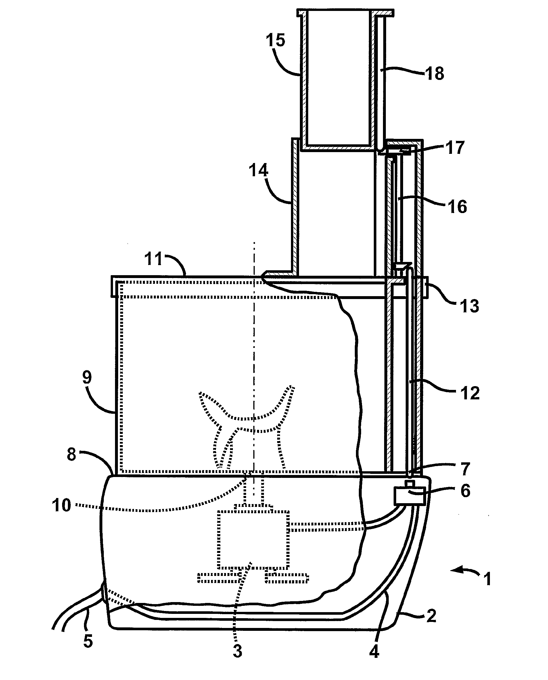
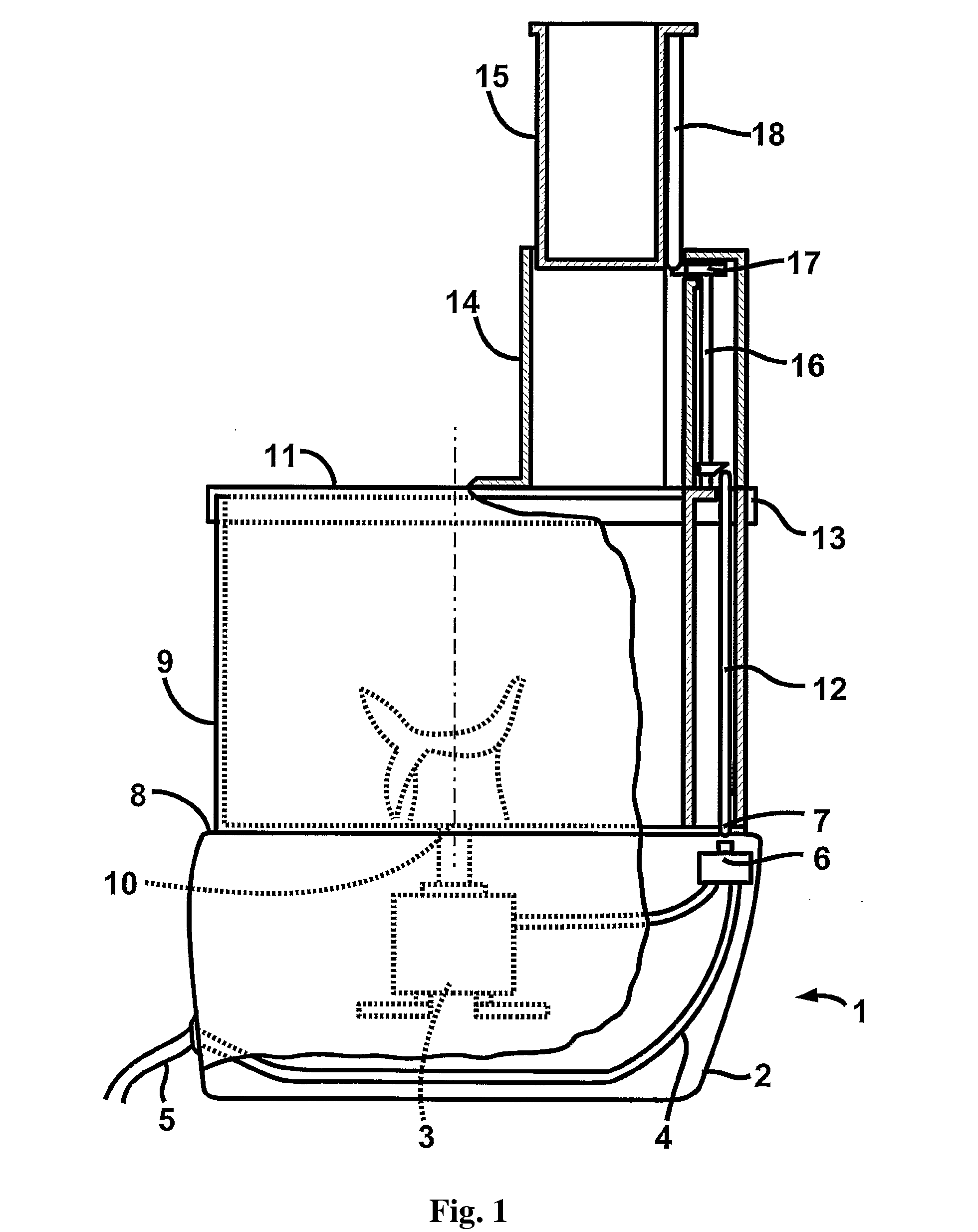
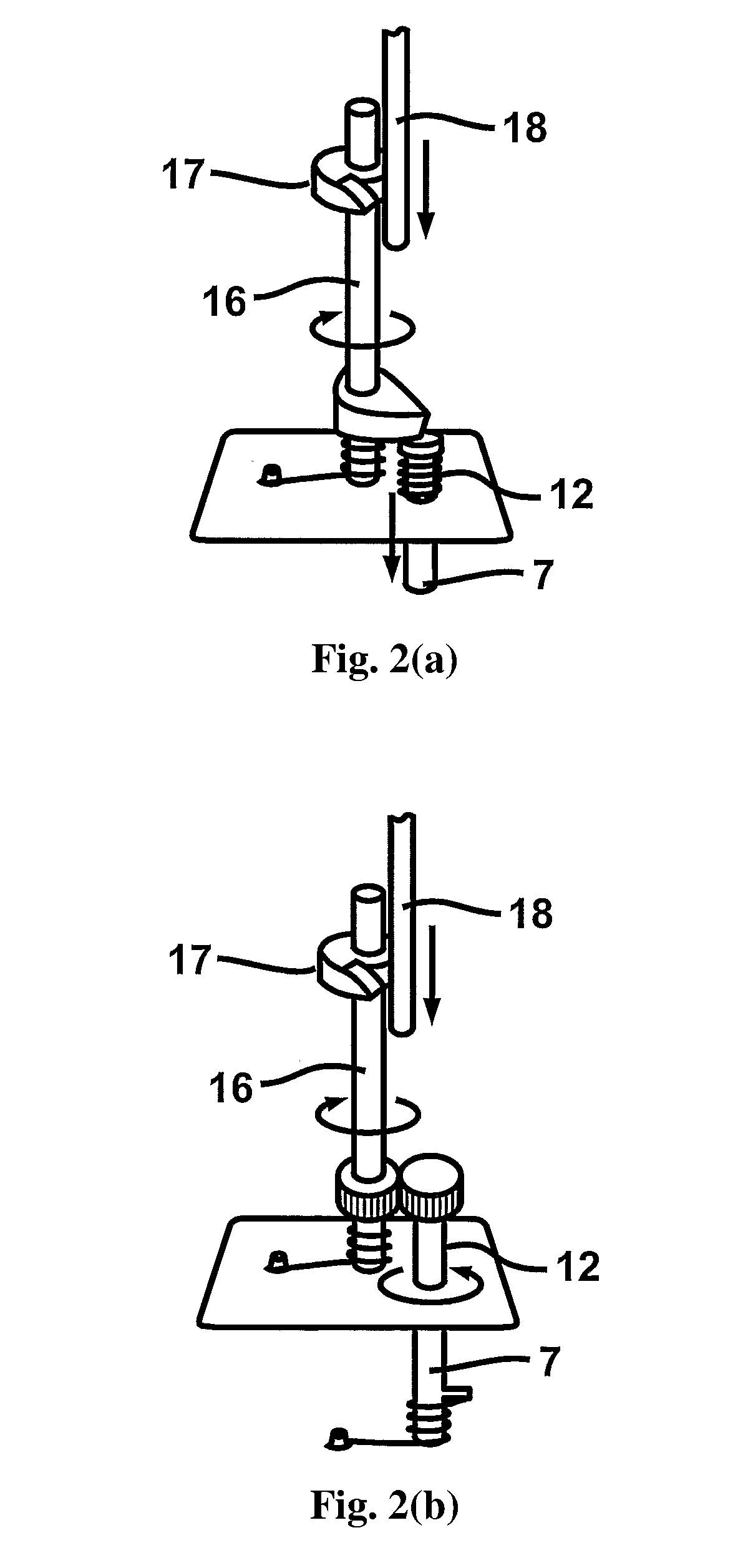
[0025]Typically, prior art interlock systems capable of preventing operation of a domestic food mixing or processing appliance until a lid or cover has been properly located on an otherwise open receptacle in which a processing tool is driven to process foodstuffs, use a push-rod which runs down a side-wall of the receptacle. Usually the upper end of the push-rod is disposed within a shrouded location atop the side-wall, and its lower end protrudes through a small aperture into a base casing which supports the receptacle in use and which also houses a drive motor for the appliance. In such systems, a normally open cut-off switch, or an actuator for such a switch, is also disposed within the housing and close to the aperture. The rod is spring-loaded away from the cut-off switch or its actuator. In use, when the lid or cover is rotated to set it in its correct operative position upon the receptacle, an actuator formed on the rim of the lid or cover enters (through a suitably located ...
PUM
 Abstract
Description
Claims
Application Information