
Paintball loading device

a technology of loading device and paintball, which is applied in the direction of launching weapon, white arms/cold weapons, weapons types, etc., can solve the problems of inability to completely eliminate jamming, and disadvantage of adding height profil

Inactive Publication Date: 2007-01-18
VAN DORSSER JEFFERY F +1
View PDF6 Cites 83 Cited by
  • Summary
  • Abstract
  • Description
  • Claims
  • Application Information

AI Technical Summary

Problems solved by technology

Although all of the above mentioned patents achieve their intended purpose, they do so only satisfactorily.
There are three disadvantages to all of these designs.
Primarily, they fail to completely eliminate jamming (and hence do not eliminate the root cause of the problem).
Secondly, all are designs that still rely on gravity to effectively deliver paintballs to the breach of the paintball marker as the agitating devices only partially prevents jamming.
In the sport of paintball, a hit on the marker counts as a hit on the player, thus the added height profile is a disadvantage.
Thirdly, relying on gravity to deliver paintballs to the breach introduces an obvious limitation.
It is also incapable of effectively feeding paintballs up through a feed tube against the force of gravity and is therefore still partially dependent on gravity.
Furthermore, should a paintball break within the loader during use, cleaning out the feed mechanism is not easily accomplished.
While the loading device of U.S. Pat. No. 5,816,232 does impart a directional force on the paintballs via a horizontally mounted rotating paddle wheel which forcibly engages paintballs, this force is insufficient to feed the paintballs reliably against the force of gravity.
Although this particular loader effectively feeds paintballs without the aid of gravity, it has four key limitations.
This particular design will not function on any other marker and thus has limited functionality.
Another major drawback with this design is speed.
By virtue of its many mechanical linkages it is not capable of the rapid rate of fire demanded by tournament players.
It is also limited in capacity, and must have additional compartments added to accommodate more paintballs.
Lastly, like many of the previously mentioned designs, it is very difficult to clean out both on and off the field.
Lastly, it also suffers from being difficult to clean out during play should a paintball break within its internals.
Although this design would appear to be effective in feeding paintballs at a reasonable rate to the marker, it has some inherent flaws.
Firstly, due to the size of the paddle wheel the frontal area is quite large, presenting an enlarged target to an opponent.
Secondly, the internals are arranged such that should paintball breakage occur while in use, it would be virtually impossible to effectively clean during game time, since tournament style paintball games rarely last more than 15 to 20 minutes.
The need to wind the spring up to the point that more than one ball could be fed means that an excessive amount of force may be applied to the paintballs within the feed tube.
This increases the likelihood of breakage.
Repeated operation under this mode can easily wear a motor out due to heat stress in the armature windings and heat fatigue of the commutators.
While appearing at first to be an adequate solution to feeding paintballs against the force of gravity, it becomes apparent upon closer investigation that there are three primary deficiencies with this design.
Primarily, there is no provision for an adequate control system.
This method of operation is not particularly reasonable, as nearly all modern paintball markers have extremely short trigger travel, often less than 1 millimeter.
This type of control system is not adequate for contemporary markers.
The primary deficiency in this dependency is that there is an elevated risk of a paintball rupturing.
Finally, as with other hopper designs, the intricacy of the feed members are such that a ball breakage within the loader during game time would be very difficult to clean out without hindering a player's ability to contribute effectively to their team's efforts.
While this device allows for the feeding of paintballs into a paintball marker without the assistance of gravity, there are two main disadvantages in the design.
First, the device requires a marker capable of driving the cam indexing mechanism.
No mainstream marker designs currently on the market are designed for any loading device in particular.
Secondly, since it must be loaded prior to game commencement, once the supply of paintballs are depleted it is virtually useless, as the time required to reload it would prevent the user from actively participating in the game.
Finally, like many other designs, the internal design of the drive mechanism is not conducive to quick cleaning should a paintball break during game time, making the device difficult to use for the duration of the game.

Method used


Image

  • Paintball loading device
  • Paintball loading device
  • Paintball loading device

Examples


Embodiment Construction

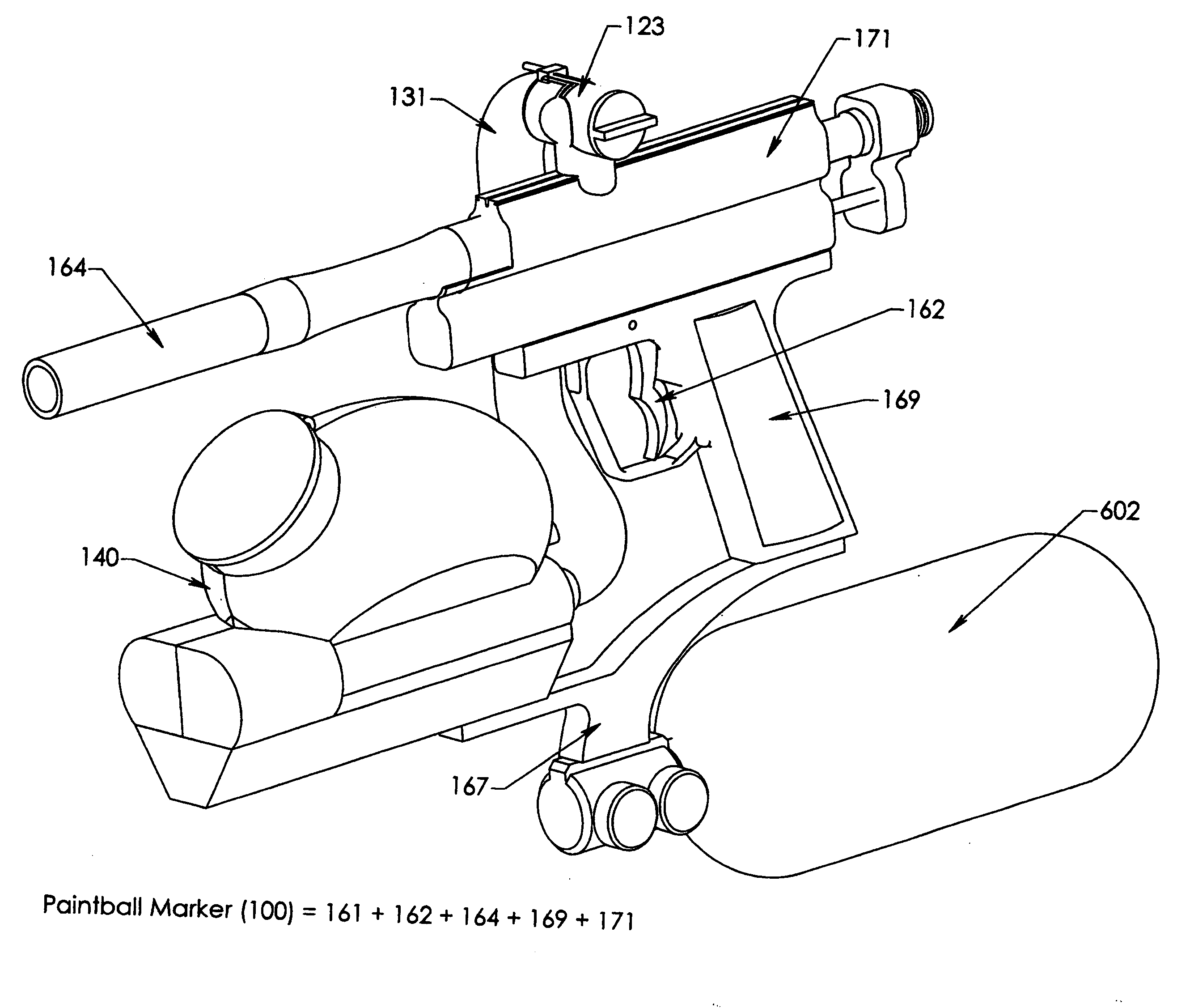
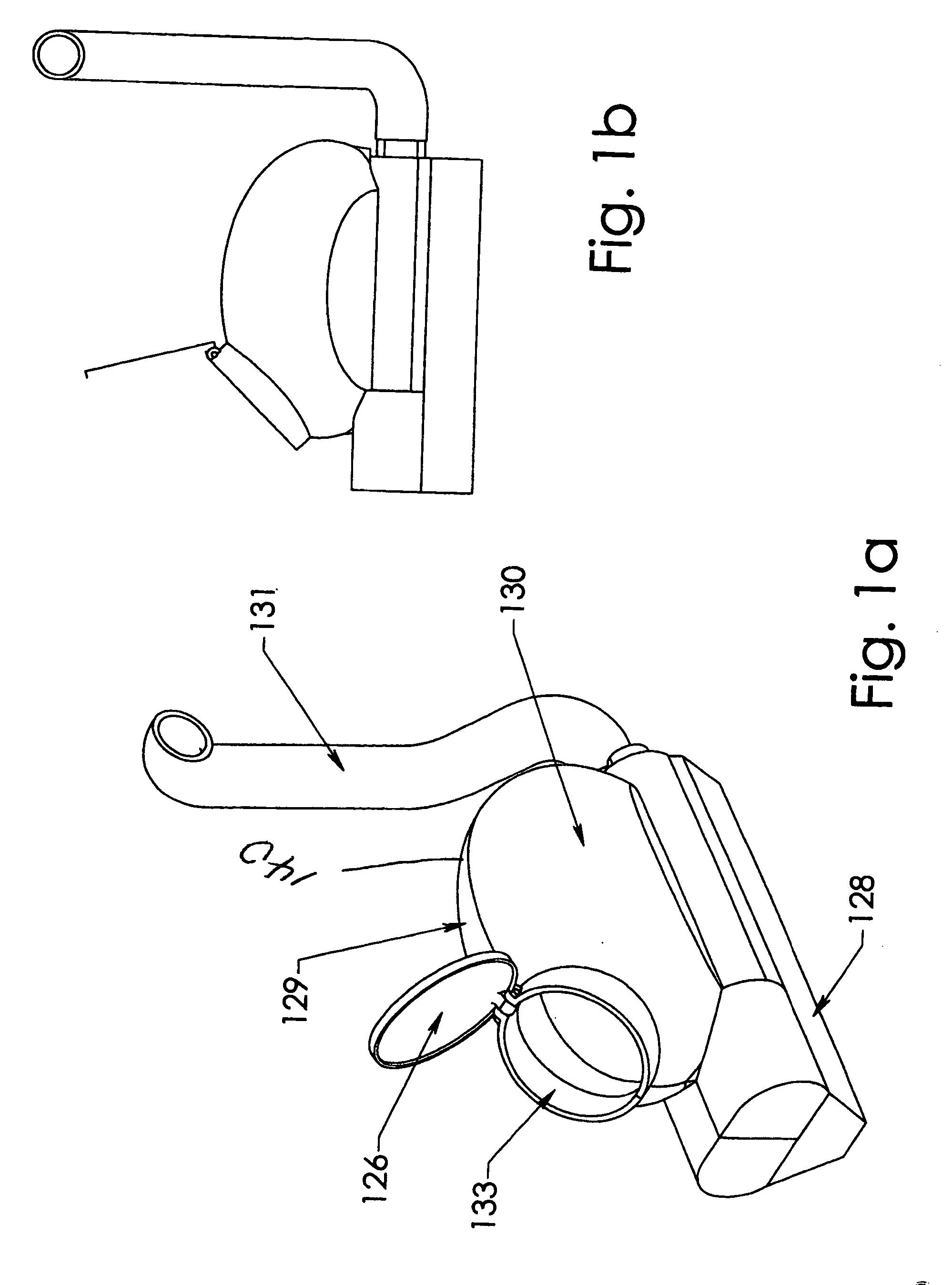
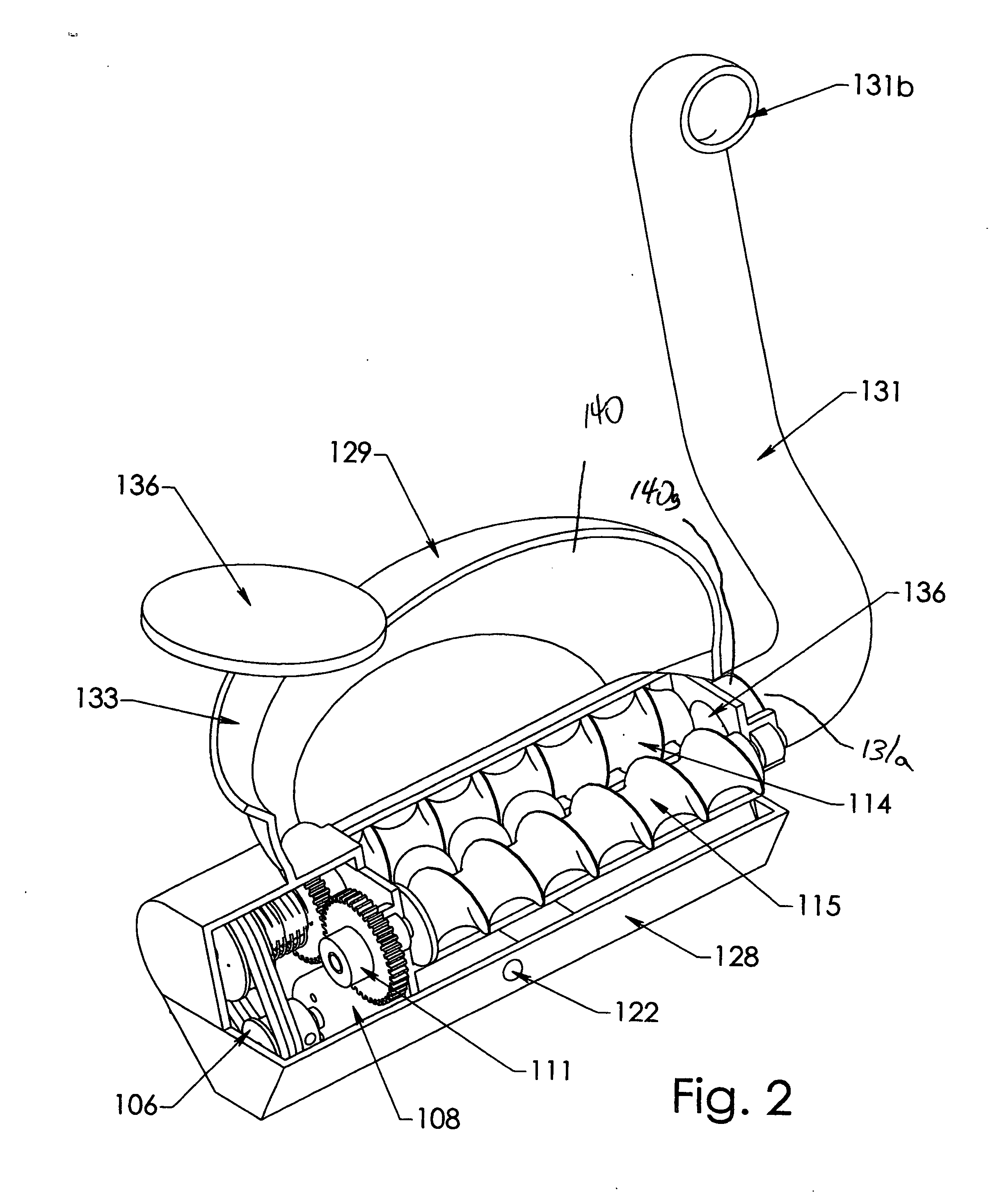
[0042] Referring firstly to FIG. 6 the present invention is an automatically fed paint ball marker, shown generally as item 11 which consists of a paintball marker 12 and an automatic paintball loading device 14. Paintball loading device 14 comprises a paintball hopper 16 having opening 18 and exit port 20. A drive housing 24 is mounted immediately below hopper 16. Drive housing 24 has an augur channel 26 containing a pair of parallel helical augurs 114 and 116 (see FIG. 9). Augur channel 26 has an exit port 136. Feed tube 131 has opposite ends 131a and 170a. End 131a is coupled to exit port 136 and end 170a is coupled to breech 170 of paintball marker 12. The augurs are coupled to drive mechanism 22. Drive mechanism 22 is configured to rotate the augurs in a counter rotating fashion in order to drive paintballs between the augurs and through feed tube 131 and into breach 170.

[0043] Drive mechanism 22 consists of an electric motor 108 coupled to pulley 106 which is in turn coupled ...


PUM


Abstract

An adaptive, force-fed paintball loading device capable of delivering paintballs to a paintball marker against the force of gravity is disclosed. The paintball loading device preferably includes a refillable compartment that is generally an oblong elliptical container holding a plurality of paintballs. Paintballs are able to flow through an opening in the lower portion of the compartment and in between two synchronously geared counter-rotating helical augers. The geometry of flutes on the counter-rotating augers causes the paintballs in the lower portion of the container to be engaged between the augers and then pushed along a channel between the augers and out through a feed tube, which is attached to a paintball marker. A DC electric motor is used to drive the augers. A speed reduction unit is employed to reduce the motor shaft speed to a level practicably used by the synchronously geared augers. A feedback control loop and dynamic coupling element are also employed to enhance the response of the loading system to changing rates of fire of the attached paintball marker. Input signals from sensors on the paintball marker and the paintball loading device may also be employed to enhance the responsiveness of the paintball loading device to the demands of the paintball marker.

Description

FIELD OF INVENTION [0001] The present invention generally relates to paintball loading devices, more specifically, it relates to a paintball loader used to forcefully deliver paintballs to a paintball marker against the force of gravity. BACKGROUND OF INVENTION [0002] The game of paintball usually involves the participation of two teams. Players on each team are armed with paintball markers that shoot small paint filled gelatin balls. The object of the game is for either of the teams to capture the opposing team's flag while at the same time eliminating as many of the opposing team's players as possible. An elimination occurs when a player is struck by a paintball. The paintball must rupture on the player to count as a “hit”. A “hit” on a player's equipment, such as their marker, also counts as an elimination. The game of paintball has experienced tremendous growth in technological advancements over the past several years. With the advent of semi automatic markers there arose a requ...

Claims


Application Information

Patent Timeline
IPC IPC(8): F41B11/02
CPCF41B11/53F41B11/57
Inventor VAN DORSSER, JEFFERY F.VAN DORSSER, TREVOR
Owner VAN DORSSER JEFFERY F
Learn More