Eureka AIR delivers breakthrough ideas for toughest innovation challenges, trusted by R&D personnel around the world.

Two-phase operation of plasma chamber by phase locked loop

a plasma chamber and phase locking technology, applied in the direction of electric discharge tubes, coatings, chemical vapor deposition coatings, etc., can solve the problem of non-uniform application of rf power

Inactive Publication Date: 2013-10-31
APPLIED MATERIALS INC
View PDF16 Cites 208 Cited by
  • Summary
  • Abstract
  • Description
  • Claims
  • Application Information

AI Technical Summary

Benefits of technology

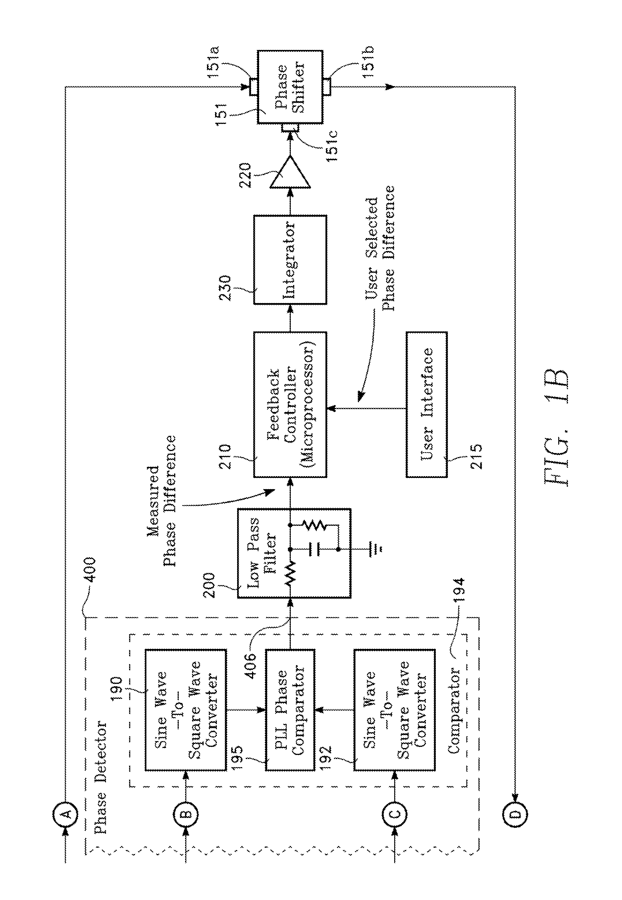
The patent describes a plasma reactor for processing a workpiece that includes a vacuum chamber, a workpiece support, and electrodes. The reactor includes a phase detector that detects the phase difference between signals from the top and bottom electrodes, and a feedback controller that adjusts the phase to match a user-selected difference. The technical effects of this invention include improved precision and accuracy in the plasma process, as well as increased efficiency and control of the plasma reactor.

Problems solved by technology

Nora-uniformity in plasma processing can arise from non-uniformities or asymmetries in the reactor chamber electrical characteristics, non-uniformity in the distribution of process gases and flow rates, or non-uniformity in the application of RF power, for example.

Method used


Image

  • Two-phase operation of plasma chamber by phase locked loop
  • Two-phase operation of plasma chamber by phase locked loop
  • Two-phase operation of plasma chamber by phase locked loop

Examples


Embodiment Construction

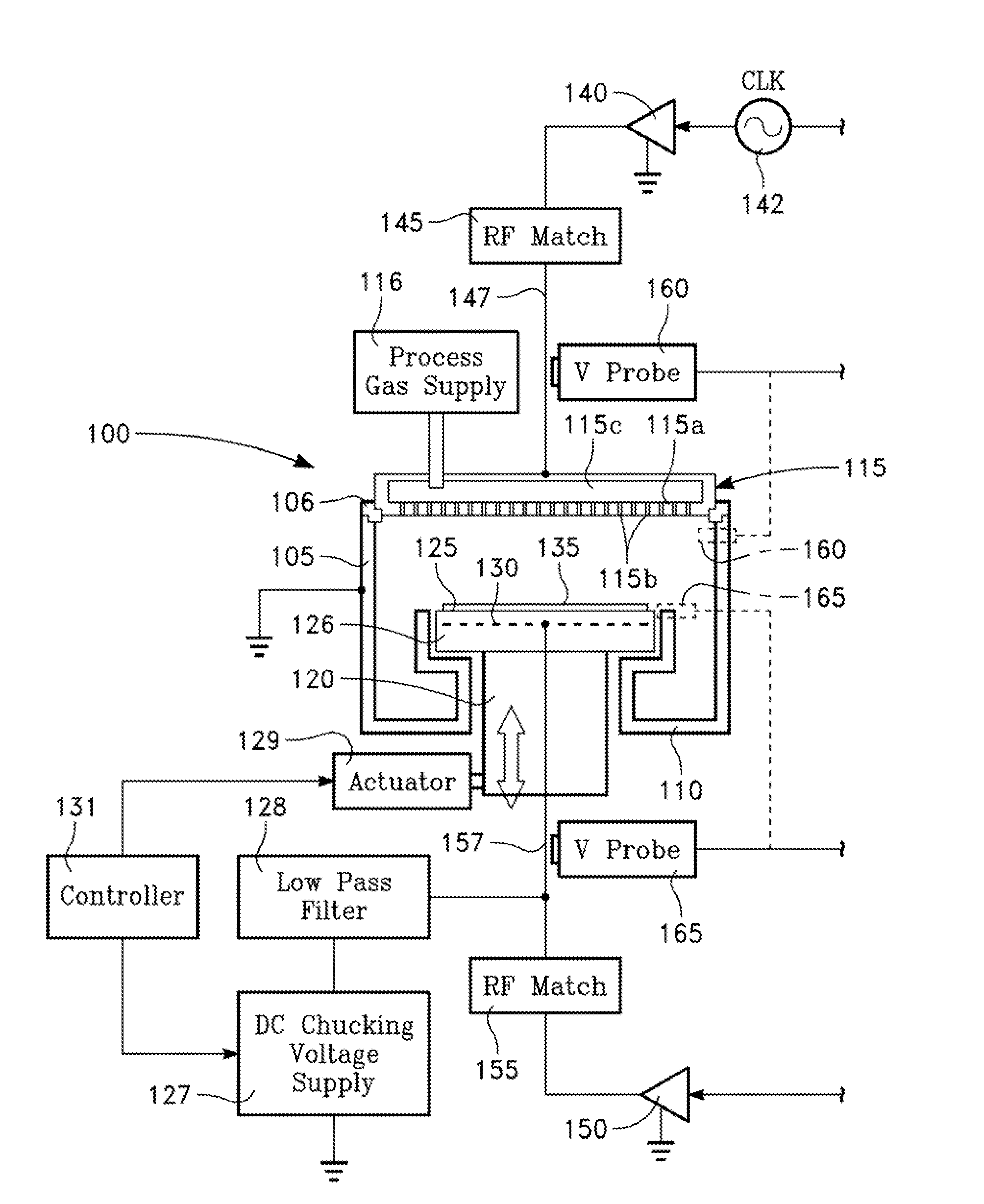
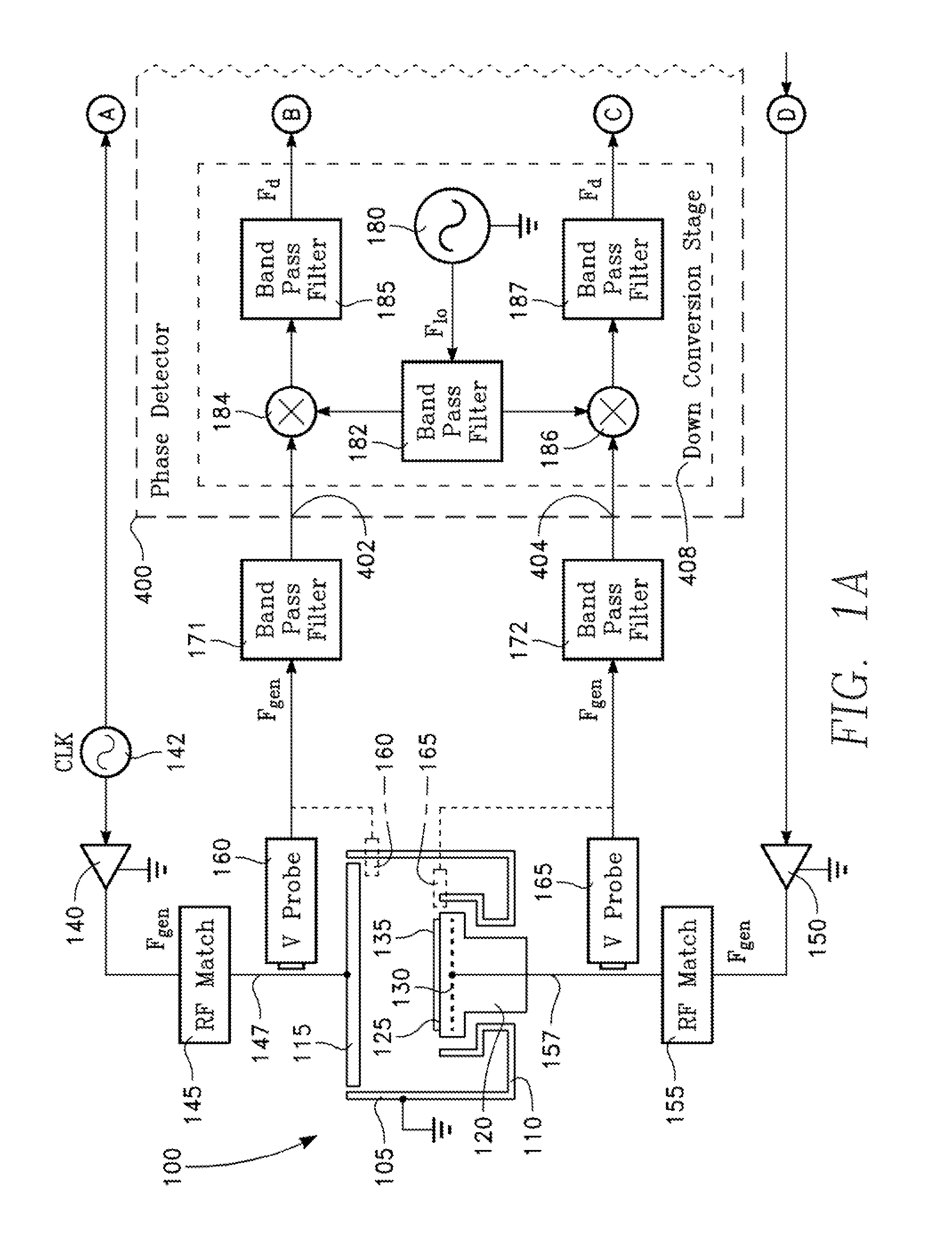
[0016]The plasma reactor described herein provides control of radial distribution of plasma ion density by controlling the phase difference between RF source power waveforms applied to opposing RF source power applicators above and below the surface of the workpiece being treated. In the description that follows, the opposing RF source power applicators are opposing electrodes. The RF power distribution at the surface of the workpiece affects plasma ion density, which in turn affects process rate distribution. The process may be an etch process or a deposition process, for example.

[0017]In general, RF power of the same frequency is applied to the two opposing electrodes. Maintaining a phase difference of 180° between the RF waveforms applied to the opposing electrodes causes the electric field lines to extend in a generally straight manner between the opposing electrodes, resulting in a center-high (edge-low) radial distribution of plasma ion density at the workpiece surface. Mainta...


PUM

PropertyMeasurementUnit
phase angleaaaaaaaaaa
frequencyaaaaaaaaaa

Abstract

Plasma distribution is controlled in a plasma reactor by controlling the phase difference between opposing RF electrodes, in accordance with a desired or user-selected phase difference, by a phase-lock feedback control loop.

Description

CROSS-REFERENCE TO RELATED APPLICATIONS[0001]This application claims the benefit of U.S. Provisional Application Ser. No. 61 / 638,846, filed Apr. 26, 2012 entitled TWO-PHASE OPERATION OF PLASMA CHAMBER BY PHASE LOCKED LOOP, by Satoru Kobayashi, et al.BACKGROUND OF THE INVENTION[0002]Plasma processing of a workpiece in the fabrication of integrated circuits, plasma displays, solar panels or the like requires uniform treatment of each workpiece across its surface. For example, in plasma processing of semiconductor wafers, feature sizes are on the order of nanometers, and uniformity and control of plasma ion distribution density across the workpiece surface is critical. Uniformity of distribution of etch rate or deposition rate across the surface of workpiece is required, as workpiece size (e.g., semiconductor wafer diameter) is increasing, and feature sizes are decreasing. Nora-uniformity in plasma processing can arise from non-uniformities or asymmetries in the reactor chamber electri...

Claims


Application Information

Patent Timeline
Patent Type & Authority Applications(United States)
IPC IPC(8): C23C16/505B05C9/00
CPCC23C16/505B05C9/00H01J37/32091H01J37/32174H01J37/3299
Inventor KOBAYASHI, SATORUWONG, LAWRENCELIU, JONATHANYANG, YANGRAMASWAMY, KARTIKRAUF, SHAHIDNEVIL, SHANE C.BERA, KALLOLCOLLINS, KENNETH S.
Owner APPLIED MATERIALS INC
Why Eureka
Eureka Blog
Learn More