Microwave processing apparatus

Inactive Publication Date: 2010-07-15
PANASONIC CORP
View PDF18 Cites 148 Cited by
  • Summary
  • Abstract
  • Description
  • Claims
  • Application Information

AI Technical Summary

Benefits of technology

[0049]According to the present invention, the electromagnetic wave distribution between the first radiator and the second radiator that are opposite each other can be changed by changing the phase difference between the microwaves respectively radiated from the first and second radiators. Consequently, it is possible to feed the microwaves to the object in a desired electro

Problems solved by technology

Here, when the electromagnetic wave distributions of the microwaves inside t

Method used


Image

  • Microwave processing apparatus
  • Microwave processing apparatus
  • Microwave processing apparatus

Examples


first embodiment

[1] First Embodiment

[0067](1-1) Outline of Configuration and Operations of Microwave Oven

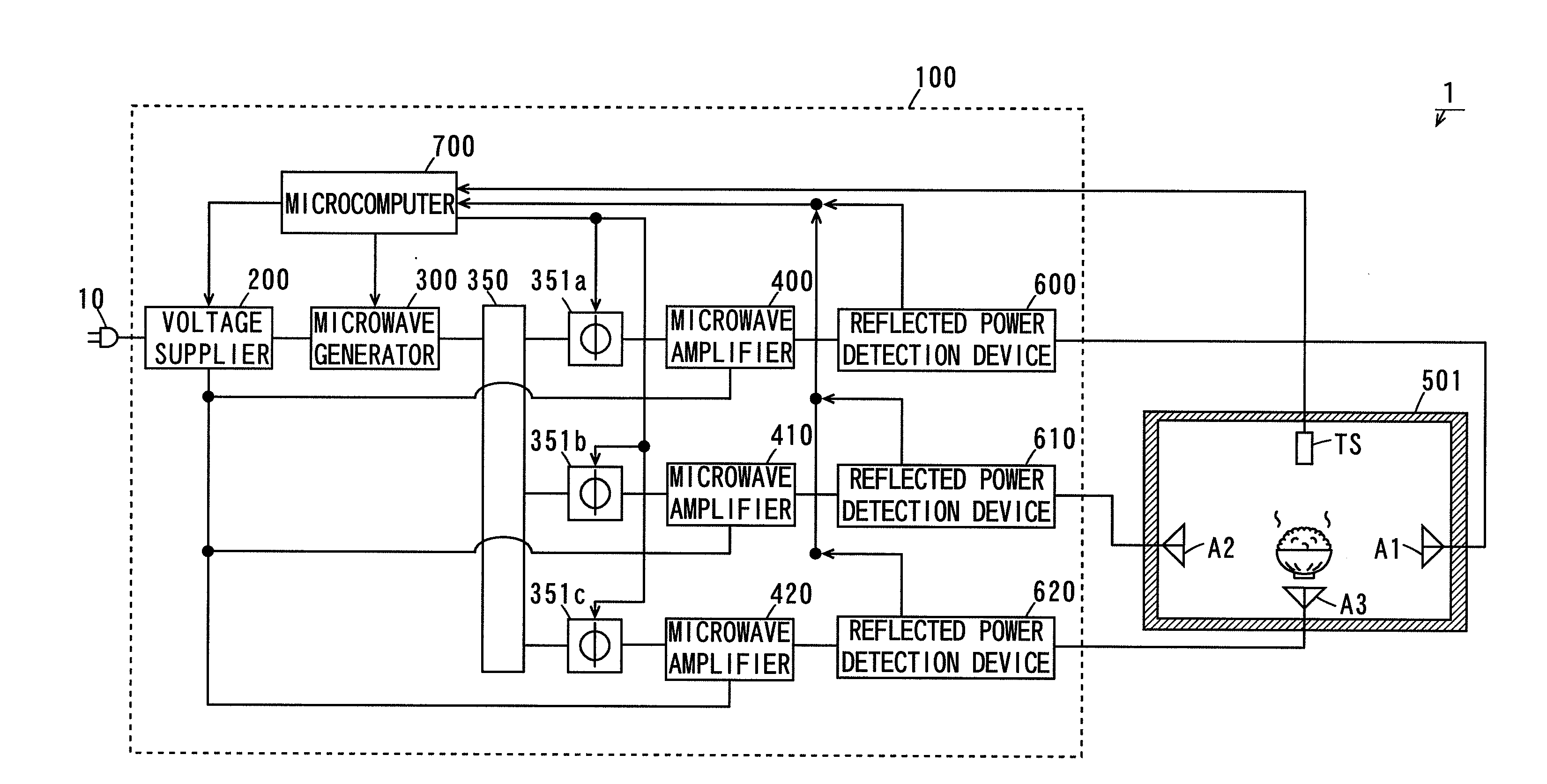
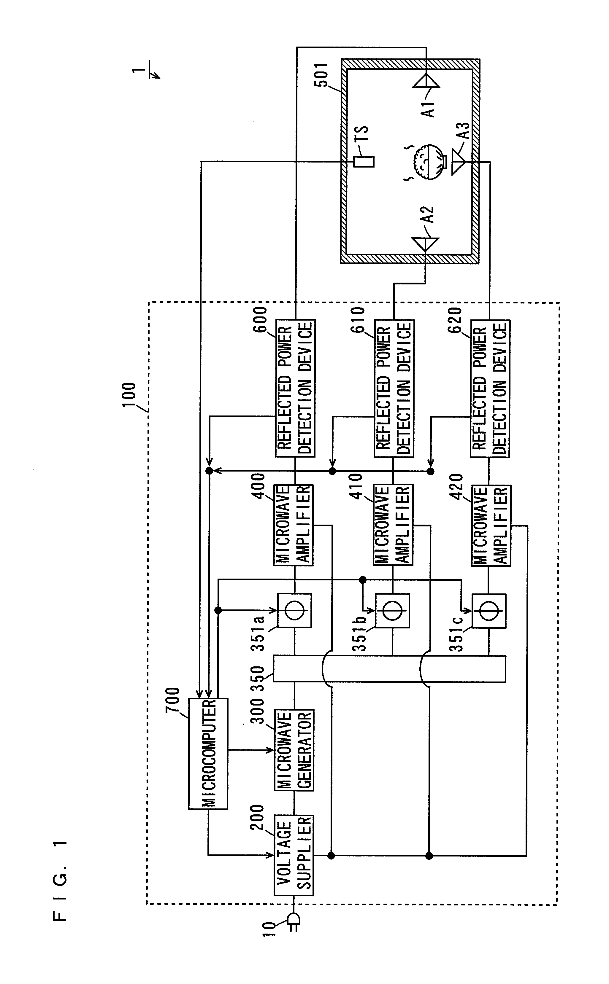
[0068]FIG. 1 is a block diagram showing the configuration of a microwave oven according to a first embodiment. As shown in FIG. 1, a microwave oven 1 according to the present embodiment includes a microwave generation device 100 and a case 501. Three antennas A1, A2, and A3 are provided in the case 501.

[0069]In the present embodiment, the two antennas A1 and A2 out of the three antennas A1, A2, and A3 within the case 501 are opposite each other in a horizontal direction.

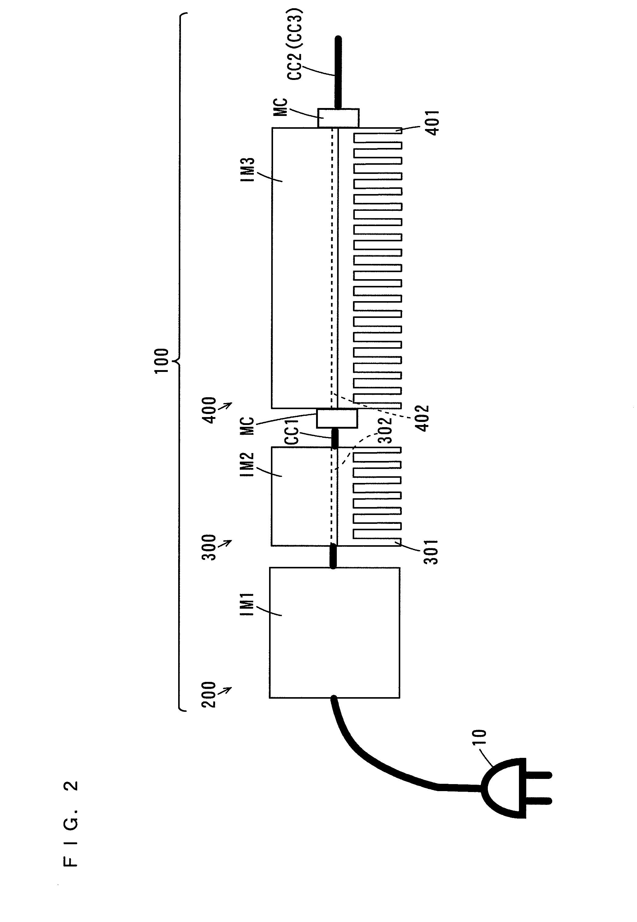
[0070]The microwave generation device 100 includes a voltage supplier 200, a microwave generator 300, a power distributor 350, three phase variators 351a, 351b, and 351c having the same configuration, three microwave amplifiers 400, 410, and 420 having the same configuration, three reflected power detection devices 600, 610, and 620 having the same configuration, and a microcomputer 700. The microwave generation device 100 is con...

second embodiment

[2] Second Embodiment

[0223]A microwave oven according to a second embodiment differs from the microwave oven 1 according to the first embodiment in the following points.

[0224](2-1) Outline of Configuration and Operations of Microwave Oven

[0225]FIG. 13 is a block diagram showing the configuration of the microwave oven according to the second embodiment. As shown in FIG. 13, a microwave oven 1 according to the second embodiment differs from the microwave oven 1 (FIG. 1) according to the first embodiment in the configuration of a microwave generation device 100.

[0226]In the microwave oven 1 according to the present embodiment, the microwave generation device 100 includes a voltage supplier 200, two microwave generators 300 and 310 having the same configuration, a power distributor 360, two phase variators 351a and 351b having the same configuration, three microwave amplifiers 400, 410, and 420 having the same configuration, three reflected power detection devices 600, 610, and 620 havi...

third embodiment

[3] Third Embodiment

[0239]A microwave oven according to a third embodiment differs from the microwave oven 1 according to the first embodiment in the following points.

[0240](3-1) Outline of Configuration and Operations of Microwave Oven

[0241]FIG. 14 is a block diagram showing the configuration of the microwave oven according to the third embodiment. As shown in FIG. 14, a microwave oven 1 according to the third embodiment differs from the microwave oven 1 (FIG. 1) according to the first embodiment in the configuration of a microwave generation device 100.

[0242]In the microwave oven 1 according to the present embodiment, the microwave generation device 100 includes a voltage supplier 200, a microwave generator 300, three power distributors 350A, 350B, and 350C having the same configuration, four phase variators 351a, 351b, 351c, and 351d having the same configuration, four microwave amplifiers 400, 410, 420, and 430 having the same configuration, four reflected power detection device...


PUM


Abstract

A microwave oven includes a microwave generation device and a case. Three antennas are provided in the case. The two antennas are opposite each other along a horizontal direction. In the microwave generation device, a power distributor almost equally distributes a microwave generated by a microwave generator among phase variators. Each of the phase variators adjusts the phase of the fed microwave. This causes a phase difference between microwaves respectively radiated from the opposite two antennas to change. The microwaves are respectively radiated from the antennas.

Description

TECHNICAL FIELD[0001]The present invention relates to a microwave processing apparatus that processes an object using a microwave.BACKGROUND ART[0002]Examples of apparatuses that process objects using microwaves include microwave ovens. In the microwave ovens, microwaves generated from microwave generators are radiated to heating chambers made of metals. This causes objects arranged inside the heating chambers to be heated using the microwaves.[0003]Conventionally, magnetrons have been used as the microwave generation devices in the microwave ovens. In this case, the microwaves generated by the magnetrons are fed into the heating chambers through waveguides.[0004]Here, when the electromagnetic wave distributions of the microwaves inside the heating chambers are non-uniform, the objects cannot be uniformly heated. Therefore, a microwave oven that feeds a microwave generated by a magnetron into a heating chamber through first and second waveguides has been proposed (see Patent Documen...

Claims


Application Information

Patent Timeline
IPC IPC(8): H05B6/68H05B6/72
CPCH05B6/686H05B2206/044H05B6/72H05B6/705
Inventor NOBUE, TOMOTAKAMIHARA, MAKOTOYASUI, KENJI
Owner PANASONIC CORP
Why Eureka
Try Eureka