Inductively Coupled Plasma Reactor

a plasma reactor and inductive coupling technology, applied in chemical/physical/physical-chemical processes, energy-based chemical/physical/physical-chemical processes, electric discharge tubes, etc., can solve the problems of limiting the power supply of the antenna, limiting the widening structure of the antenna, and limiting the effect of widening the antenna structure and reducing the loss of magnetic flux

Inactive Publication Date: 2008-05-29
GENERAL CO LTD
View PDF22 Cites 24 Cited by
  • Summary
  • Abstract
  • Description
  • Claims
  • Application Information

AI Technical Summary

Benefits of technology

[0012]Therefore, the present invention provides a plasma reactor capable of generating plasma of a high density which has a high control ability on plasma ion energy and a uniform large area by employing the advantages of inductively coupled plasma and capacitively coupled plasma.
[0013]The present invention also provides a plasma reactor capable of generating plasma of a high density which has a high control ability on plasma ion energy and a uniform large area by improving the magnetic flux transferring efficiency of an antenna.
[0014]The present invention also provides a plasma reactor capable of generating uniform plasma of a high density by increasing the transfer efficiency of a magnetic flux from a radio frequency antenna into the interior of a vacuum chamber and by uniformly supplying process gas.
[0017]The capacitive and inductive coupling of the plasma reactor generates plasma to allow generation of plasma in the vacuum chamber and accurate control of plasma ion energy. Since the radio frequency antenna is covered by a magnetic core, the strongly-collected magnetic flux can be transferred into the interior of the vacuum chamber and the loss of the magnetic flux can be minimized.

Problems solved by technology

However, the increase on the electric power of the radio frequency causes ion impact energy.
As a result, the electric power of the radio frequency is limited to prevent damage due to an ion impact.
However, there is a limit in widening the structure of the antenna or in increase the power supplied to the antenna in order to obtain the plasma of a large area.

Method used


Image

  • Inductively Coupled Plasma Reactor
  • Inductively Coupled Plasma Reactor
  • Inductively Coupled Plasma Reactor

Examples


first embodiment

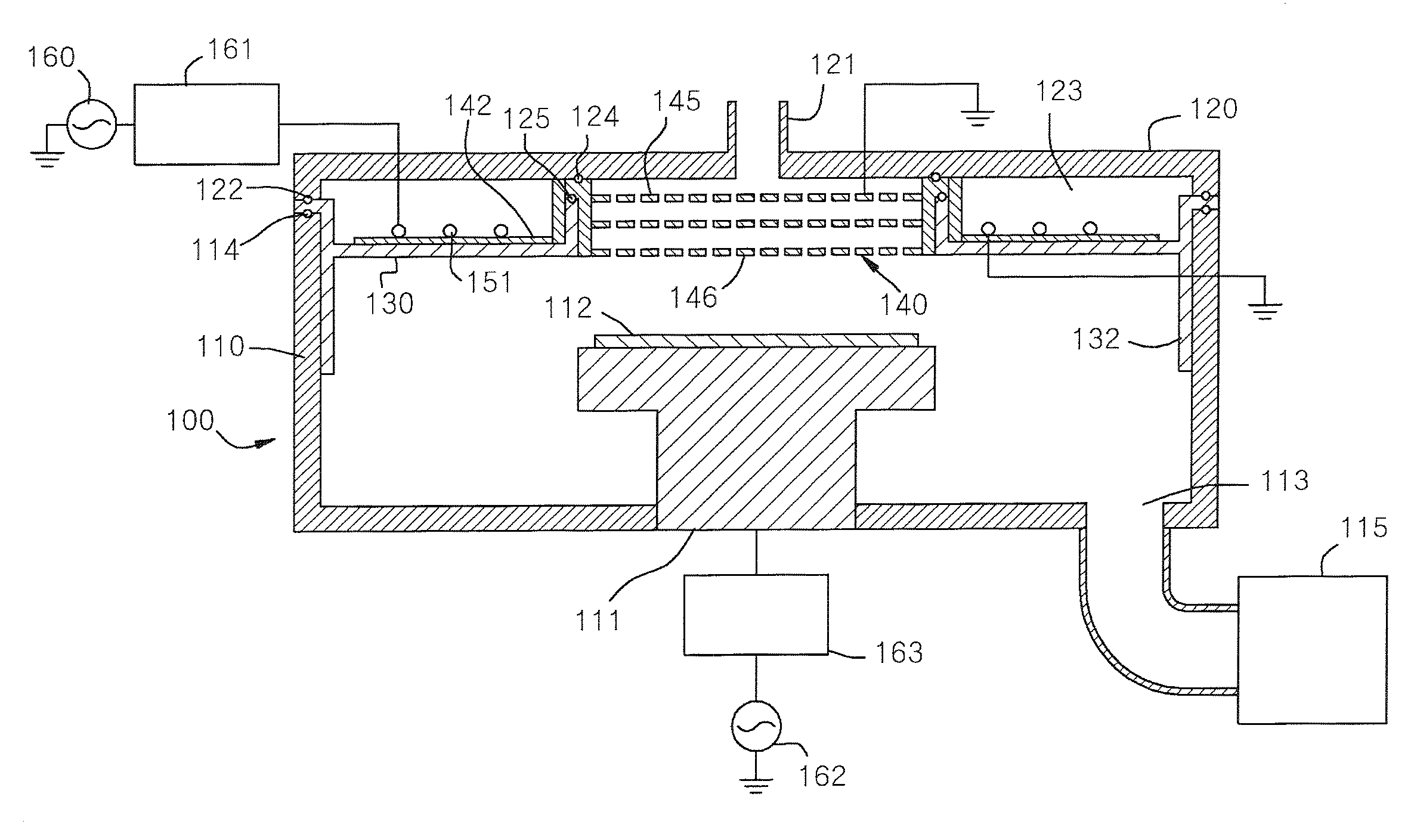
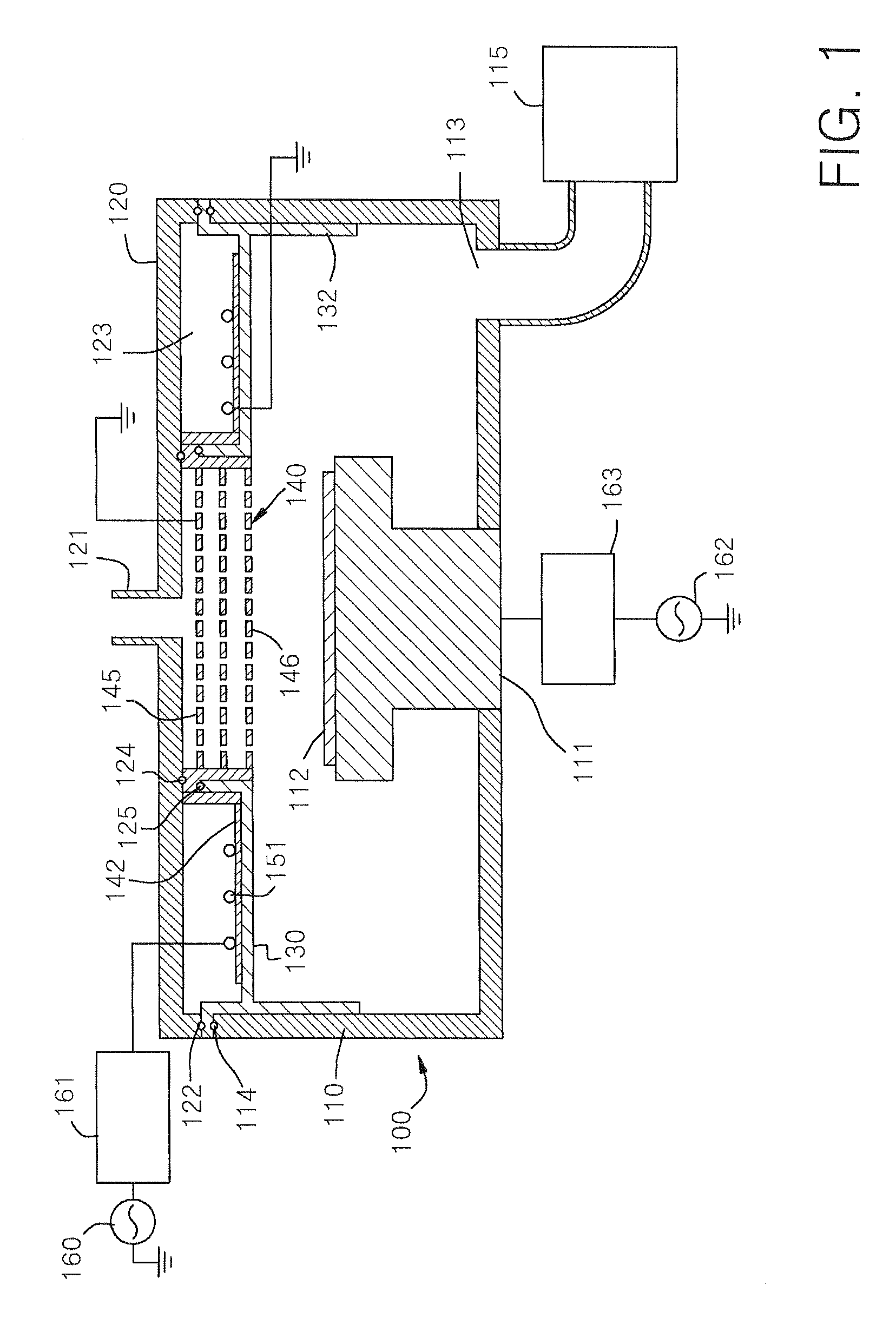
[0047]FIG. 1 is a cross-sectional view of a plasma reactor according to the present invention.

[0048]Referring to FIG. 1, the plasma reactor includes a vacuum chamber 100 having a lower body 110 and an upper cover 120. A substrate support 111 on which a treated substrate 112 is positioned is provided in the interior of the vacuum chamber 100. The lower body 110 includes a gas outlet 113 for exhausting gas and the gas outlet 113 is connected to a vacuum pump 115. The treated substrate 112 is a silicon wafer substrate for manufacturing a semiconductor device and a glass substrate for manufacturing a liquid crystal display or a plasma display.

[0049]The lower body 110 is formed of a metal material such as aluminum, stainless steel, and copper. Further, the lower body 110 may be formed of a coated material, e.g. anodized aluminum or aluminum coated with nickel. Further, the lower body 110 may be formed of a refractory metal. As an alternative, the lower body 110 may be formed of an electr...

second embodiment

[0076]FIG. 8 is a cross-sectional view of a plasma reactor according to the present invention. FIG. 9 is a view illustrating an arrangement structure of the radio frequency antenna installed at an upper portion of the plasma reactor of FIG. 8 and the gas shower head.

[0077]Referring to FIGS. 8 and 9, the plasma reactor according to the second embodiment of the present invention has a structure basically the same as the above-mentioned first embodiment. Therefore, the description of the same constitution will not be repeated. However, in the plasma reactor according to the second embodiment, the structure of the vacuum chamber 100a is rather different from the vacuum chamber 100 of the first embodiment. In the vacuum chamber 100a of the plasma reactor according to the second embodiment, a dielectric window 130 provided at an upper portion of a lower body 110 also functions as an upper cover. A cover member 126 covering the radio frequency antenna 151 entirely is provided at an upper p...

third embodiment

[0080]FIG. 11 is a cross-section of a plasma reactor according to the present invention.

[0081]Referring to FIG. 11, the plasma reactor of the third embodiment has a basically same structure as the first embodiment. Therefore, the description of the same constitution will not be repeated. Especially, since in the plasma reactor of the third embodiment, a radio frequency antenna 151 is covered by a magnetic core 150, the magnetic flux can strongly collected and the loss of the magnetic flux can be minimized.

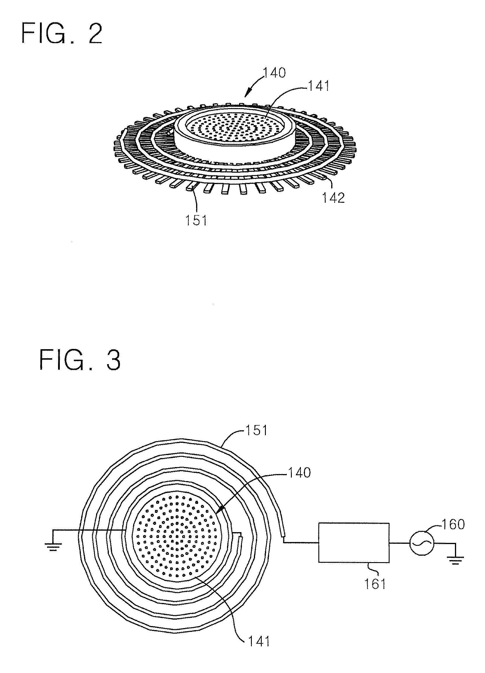
[0082]FIG. 12 is a view illustrating an arrangement structure of a radio frequency antenna installed at an upper portion of the plasma reactor and a gas shower head. FIG. 13 is a view visually illustrating a magnetic field induced in the interior of a vacuum chamber through a dielectric window by a radio antenna and a magnetic core.

[0083]Referring to FIG. 12, the radio frequency antenna 151 is installed in a flat plate spiral structure about a gas shower head 140 and is covered by ...


PUM


Abstract

There is provided a plasma reactor comprising: a vacuum chamber having a substrate support on which a treated substrate is positioned; a gas shower head supplying gas into the interior of the vacuum chamber; a dielectric window installed at an upper portion of the vacuum chamber; and a radio frequency antenna installed above the dielectric window. The gas shower head and the substrate support are capacitively coupled to plasma in the interior of the vacuum chamber and the radio frequency antenna is inductively coupled to the plasma in the interior of the vacuum chamber. The capacitive and inductive coupling of the plasma reactor allows generation of plasma in a large area inside the vacuum chamber more uniformly and more accurate control of plasma ion energy, thereby increasing the yield and the productivity. The plasma reactor includes a magnetic core installed above the dielectric window so that an entrance for a magnetic flux faces the interior of the vacuum chamber and covers the radio frequency antenna. Since the radio frequency antenna is covered by the magnetic core, the magnetic flux can be more strongly collected and the loss of the magnetic flux can be minimized.

Description

CROSS-REFERENCE TO RELATED APPLICATION[0001]This application claims the benefit of Korean Patent Applications No. 2006-45478, filed 22 May 2006, No. 2006-45509, filed 22 May 2006 and No. 2006-45833, filed 22 May 2006, the disclosure of which is hereby incorporated herein by reference in its entirety.BACKGROUND OF THE INVENTION[0002]1. Technical Field[0003]The present invention relates to a radio frequency plasma source, and more particularly, to an inductively coupled plasma reactor capable of uniformly generating plasma of a high density.[0004]2. Discussion of Related Art[0005]Plasma is highly ionized gas including the same number of positive ions and electrons. Plasma discharge is used in gas excitation for generating ions, free radicals, atoms, and molecules. Active gas is widely used in various fields, and particularly is used in semiconductor fabrication processes such as etching, deposition, cleaning, and ashing.[0006]There are various plasma sources for generating plasma, and...

Claims


Application Information

Patent Timeline
Patent Type & Authority Applications(United States)
IPC IPC(8): B01J19/08
CPCH01J37/32082H01J37/3266H01J37/321H01J37/32091H01J37/3211H01J37/32119H01J37/32128H01J37/32137H01J37/32146H01J37/32155H01J37/32165H01J37/32174H01J37/32183H01J37/32449
Inventor CHOI, DAE-KYU
Owner GENERAL CO LTD
Why Eureka
Try Eureka