Substrate supporting member and substrate processing apparatus

a technology of supporting member and substrate, applied in the direction of coating, chemical vapor deposition coating, electric discharge tube, etc., can solve the problems of large amount of heat applied to insufficient cooling of the peripheral portion of the substrate, and inability to maintain uniform in-surface temperature, so as to achieve the effect of improving production yield

Active Publication Date: 2010-05-18
TOKYO ELECTRON LTD
View PDF10 Cites 23 Cited by
  • Summary
  • Abstract
  • Description
  • Claims
  • Application Information

AI Technical Summary

Benefits of technology

[0013]The thermal conductivity between the substrate and the substrate supporting surface may be controlled by changing a material constituting each region of the substrate supporting surface.
[0014]The thermal conductivity between the substrate and the substrate supporting surface may be controlled by changing a surface roughness of each region of the substrate supporting surface.
[0016]In accordance with the present invention, the in-surface temperature of the substrate mounted on the substrate supporting member is uniformly maintained, and accordingly, an in-surface of the substrate is uniformly processed, and a production yield is improved.

Problems solved by technology

However, in case the peripheral portion of the substrate is extended beyond the susceptor as described above, during the process, a large amount of heat is applied to the peripheral portion of the substrate, and the peripheral portion of the substrate is not cooled sufficiently.
On this account, the temperature of the substrate mounted on the susceptor becomes higher as a position on the substrate approaches the peripheral portion of the substrate, and thus, the in-surface temperature is not maintained uniformly.

Method used


Image

  • Substrate supporting member and substrate processing apparatus
  • Substrate supporting member and substrate processing apparatus
  • Substrate supporting member and substrate processing apparatus

Examples


Embodiment Construction

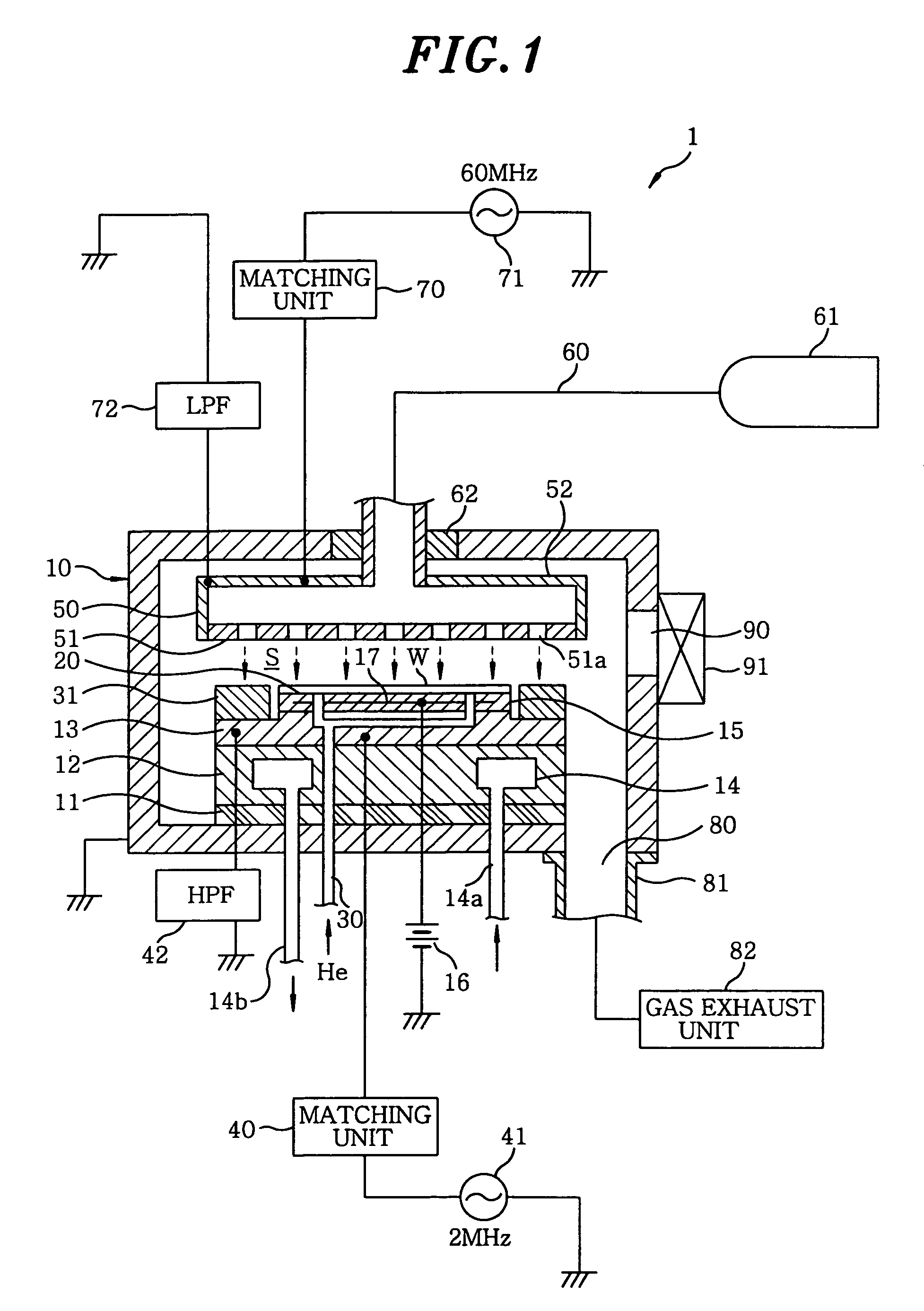
[0024]Hereinafter, a preferred embodiment of the present invention will be described. FIG. 1 is a longitudinal cross sectional view for schematically showing a configuration of a parallel plate type plasma processing apparatus 1 including a substrate supporting member in accordance with the present invention.

[0025]The plasma processing apparatus 1 includes a processing vessel 10 of e.g. a substantially cylindrical shape, and a processing space S is formed in the processing vessel 10. The processing vessel 10 is made of, for example, an aluminum alloy, and an inner wall surface thereof is coated with an alumina film or an yttrium oxide film. Further, the processing vessel 10 is grounded.

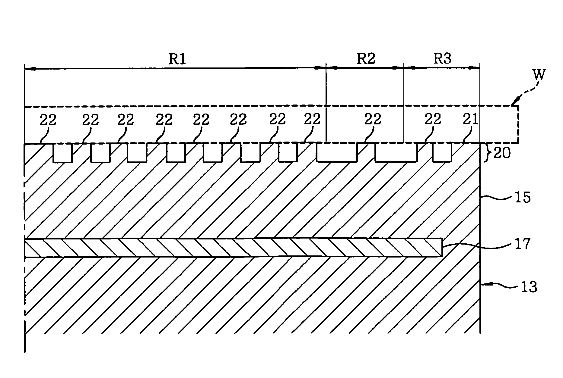
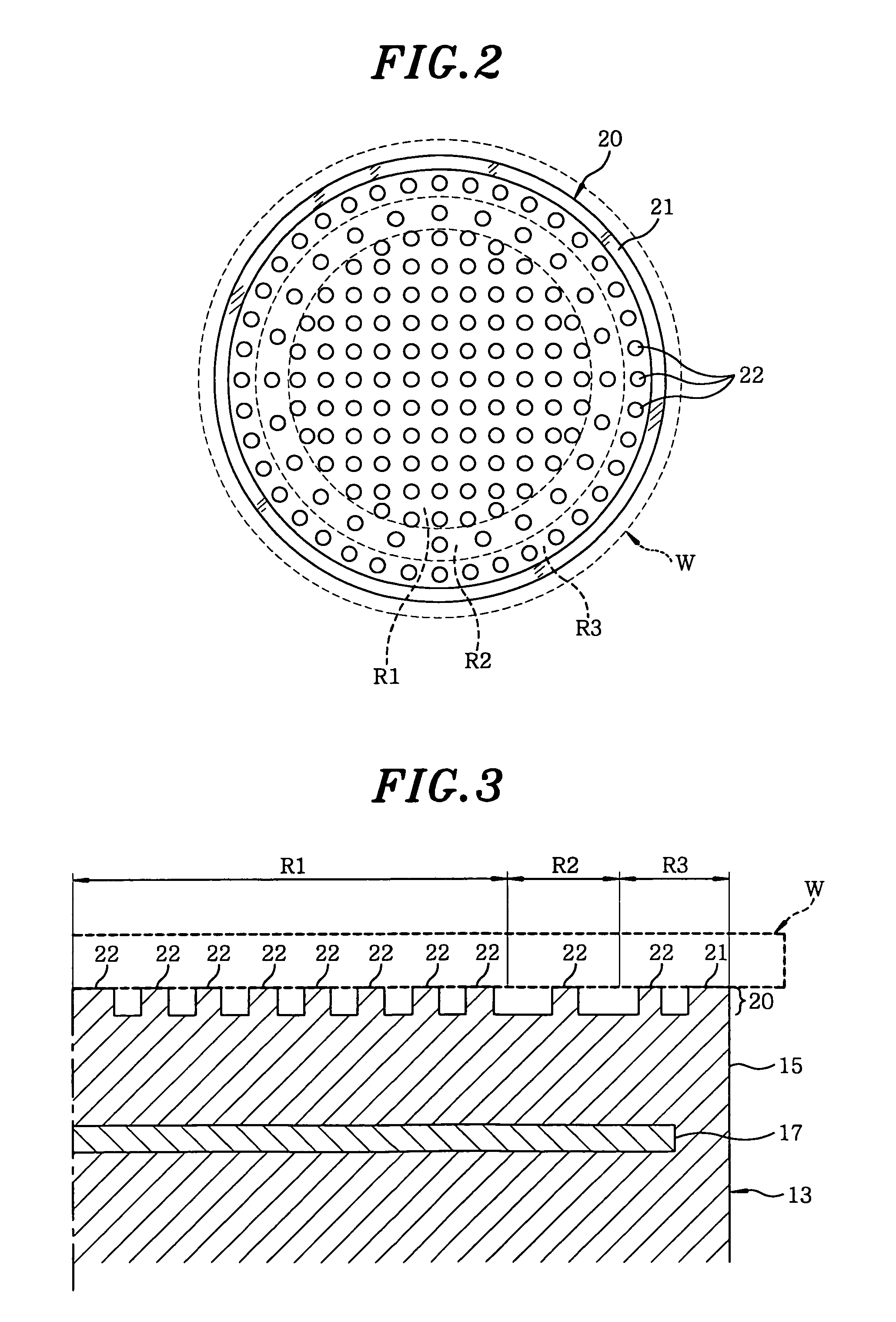
[0026]There is provided a cylindrical susceptor supporting table 12 above a central bottom portion inside the processing vessel 10, with an insulating plate 11 being interposed between them. A susceptor 13 serving as the substrate supporting member for mounting and supporting a substrate W is supporte...


PUM

PropertyMeasurementUnit
frequencyaaaaaaaaaa
frequencyaaaaaaaaaa
frequencyaaaaaaaaaa

Abstract

A substrate supporting member, and a substrate processing apparatus including the substrate supporting member are provided. The substrate supporting member for mounting and supporting a substrate on a substrate supporting surface thereof, and controlling a temperature of the substrate by thermal transfer between the substrate and the substrate supporting surface, wherein the substrate supporting surface is smaller than the substrate, and includes a central region, an intermediate region, and a peripheral region. A thermal conductivity between the substrate and the peripheral region is greater than that between the substrate and the central region which is greater than that between the substrate and the intermediate region located between the central region and the peripheral region.

Description

FIELD OF THE INVENTION[0001]The present invention relates to a substrate supporting member for supporting a substrate mounted thereon, and a substrate processing apparatus including the substrate supporting member.BACKGROUND OF THE INVENTION[0002]In a manufacturing process of semiconductor devices, e.g., an etching process or a film forming process is performed by using a plasma.[0003]The plasma processing using the plasma is generally performed by a plasma processing apparatus. The plasma processing apparatus includes, in a processing chamber, an upper electrode to which a high frequency power for generating the plasma is applied, a susceptor for supporting a substrate, and the like. Further, an inside of the processing chamber is depressurized to a predetermined pressure, and a processing gas is supplied into the processing chamber, and then, the high frequency power for generating the plasma is applied to the upper electrode to etch a film on the substrate by the plasma generated...

Claims


Application Information

Patent Timeline
Patent Type & Authority Patents(United States)
IPC IPC(8): C23C16/00C23F1/00H01L21/306
CPCH01J37/32724H01L21/68785H01L21/6875H01L21/67109
Inventor OOHASHI, KAORUHAYAMI, TOSHIHIRO
Owner TOKYO ELECTRON LTD
Why Eureka
Try Eureka