Substrate processing method and apparatus

a substrate and processing method technology, applied in lighting and heating apparatus, muffle furnaces, furnaces, etc., can solve the problems of steam condensation, stagnant inflow of processing gas to the gap, deterioration of apparatus and uniform processing throughput, etc., to achieve uniform processing temperature in the processing container, increase the effect of processing fluid supply and uniformity

Active Publication Date: 2005-10-11
TOKYO ELECTRON LTD
View PDF2 Cites 24 Cited by
  • Summary
  • Abstract
  • Description
  • Claims
  • Application Information

AI Technical Summary

Benefits of technology

[0027]According to the invention, by making the substrate to be processed approach the heating surface of the heater relatively and heating the substrate to the processing temperature while holding the substrate by the holder, it is possible to heat the substrate to the processing temperature in a short time. Then, after heating the substrate to the processing temperature, by separating the substrate from the heating surface of the heater to the processing position and further supplying the processing chamber of the processing container with the processing fluid, it is possible to supply the processing fluid uniformly. According to the inventions, by relatively moving the holder and the heating surface of the heater close to and apart from each other intermittently or continuously while supplying the processing chamber with the processing fluid, it is possible to make smooth approach of the processing fluid to both sides of the substrate and also possible to supply the processing fluid more uniformly.
[0028]Further, by moving the holder and the heating surface of the heater closer and farther in a direction generally perpendicular to the flowing direction of the processing fluid, it is possible to make the approach of the processing fluid to both sides of the substrate smoother. According to the inventions, by diffusing the processing fluid in the plane direction of the substrate in the processing container and further bypassing the processing fluid in a direction generally perpendicular to a diffusing surface of the substrate, it is possible to supply the substrate with the processing fluid uniformly.
[0029]Further, the processing container comprises the container body having its horizontal bottom part provided with the heater to form the heating surface, the container body having the fluid supply port and the drain port for the processing fluid, and the lid body that is movable up and down in the vertical direction of the substrate processing apparatus and is adapted so as to close an opening of the container body through the seal member, and the moving of the substrate between the adjacent position and the processing position is carried out under condition that the container body is closed by the lid body. Consequently, the withdrawal of the lid body from the container body allows the substrate to be transferred from the outside to the holder with ease. When processing the substrate, it is possible to insulate the processing chamber from the outside by closing the opening of the container body by the lid body closes through the seal member and also possible to process the substrate by heating it in a leak-tight atmosphere. In this case, since the lid body further comprises another heater, it is possible to maintain the processing temperature in the processing container more uniformly.

Problems solved by technology

In the conventional processing method, however, since the wafer is heated and processed with the processing fluid, for example, ozone while being mounted (or fixed) on the support table of the processing chamber through the designated gap of e.g. 0.1 to 0.5 mm, it is feared that the reduced gap between the wafer etc. and the support table causes the inflow of the processing gas to the gap to be stagnant to deteriorate the throughput of the apparatus and uniform processing.
Additionally, if employing ozone and vapor as the processing fluid together with a heating mechanism exhibiting deteriorated uniformity, there is the possibility that steam is condensed on both parts of a substrate and the support table to make a hindrance in processing the substrate.

Method used


Image

  • Substrate processing method and apparatus
  • Substrate processing method and apparatus
  • Substrate processing method and apparatus

Examples


second embodiment

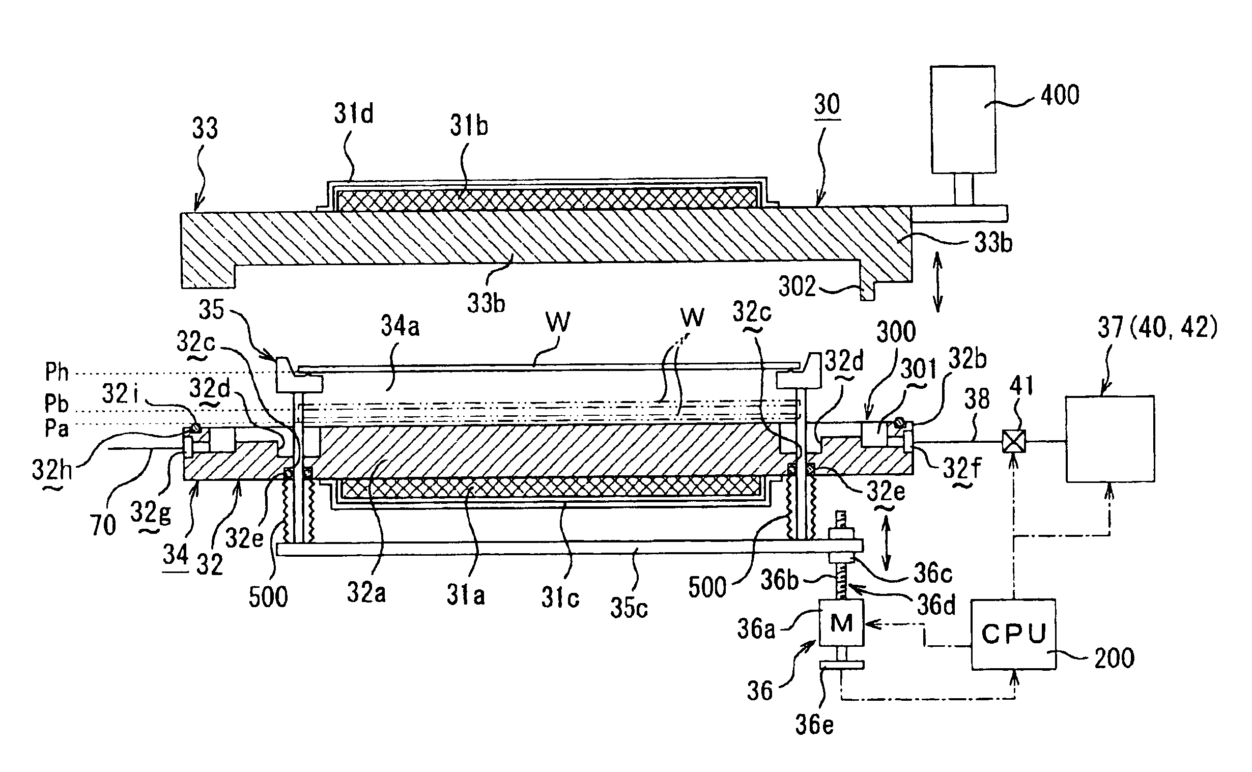
[0098] holding unit 35A is arranged so as to penetrate through-holes 33c of the rid body 33 forming the processing container 34 in a fluid-tight manner and also adapted so as to be movable close to and apart from the horizontal bottom part 32a of the container body 32. That is, the holding unit 35A consists of a plurality of (e.g. four) holding rods 35a and the corresponding holding members 35h. Each of the holding rods 35a is arranged so as to penetrate the through-hole 33c formed in the lid body 33 through an O-ring 33d as a seal member. The holding rods 35a are adapted so as to movably support the wafer W horizontally. While, each of the holding members 35h is arranged at the tip of the holding rod 35a to support the underside of the periphery of the wafer W. Outside the container body 32, the holding rods 35a are connected to the connecting member 35c. Through the intermediary of the connecting member 35c, the holding unit 35 is associated with close-and-apart moving mechanism (...

first embodiment

[0100]As similar to the first embodiment, the close-and-apart moving mechanism (moving unit) 36A is formed by a reversal motor 36a capable of normal and reverse rotations, such as step motor or servo-motor, and a ball screw mechanism 36d. The ball screw mechanism 36d has a converting part 36c in screw engagement with a screw shaft 36b connected to a drive shaft of the motor 36a through not-shown balls. Thus, the converting part 36c serves to convert the rotational movement of the reversal motor 36a to the linear movement. The motor 36a is electrically connected to controller, for example, a CPU 200. Thus, by control signals from the CPU 200, the motor 36a is rotated in normal and reverse to move the holding rods 35a of the holding unit 35A up and down. In other words, with the rotation of the motor 36a, the wafer W supported by the holding members 35h is moved close to and apart from the heater, in detail, a heating surface of the horizontal bottom part 32a of the container body 32....


PUM

PropertyMeasurementUnit
temperatureaaaaaaaaaa
heightaaaaaaaaaa
temperatureaaaaaaaaaa

Abstract

A method for heating a wafer to a predetermined temperature, the wafer being held by a holding unit and being accommodated in a processing container equipped with a heater. The wafer is heated to a processing temperature while positioning the wafer at an adjacent position that results form making the wafer approach the heating surface of the heater. After heating the wafer to the predetermined temperature, the wafer is separated from the flat bottom surface of the container body to a processing position. In this state, a processing chamber of the processing container is supplied with a processing fluid, while the holding unit and the heater are relatively moved close to and apart from each other intermittently or continuously. Accordingly, it is possible to quickly heat the substrate to a processing temperature while supplying the substrate with the processing fluid uniformly. This improves throughout and the homogenization in processing.

Description

BACKGROUND OF THE INVENTION[0001]1. Technical Field of the Invention[0002]This invention relates to substrate processing method and apparatus for processing a substrate, for example, semiconductor wafer, glass substrate for LCD, etc. with a processing fluid (e.g. ozone gas, vapor) while accommodating the substrate in a processing container.[0003]2. Description of the Related Art[0004]In the manufacturing process of semiconductor devices, generally, it is carried out to form a resist film on a substrate to be processed, for example, semiconductor water, LCD substrate, etc. by applying a resist liquid on the substrate. In connection, a designated circuit pattern is scaled down by technique of photo lithography and further transferred on the resist film for development. After the development, the resist film is removed from the substrate. Noted that the substrate, such as semiconductor water and LCD substrate, will be referred “wafer”, hereinafter.[0005]As the method for removing the r...

Claims


Application Information

Patent Timeline
Patent Type & Authority Patents(United States)
IPC IPC(8): F26B19/00F27D5/00F27B17/00
CPCF27B17/0025
Inventor MOKUO, SHORI
Owner TOKYO ELECTRON LTD
Why Eureka
Try Eureka