Communication method and system

a communication method and communication system technology, applied in the field of communication methods and systems, can solve the problems of reducing the advantages offered by traditional multi-input multi-out (mimo) system architecture, and unable to use traditional synchronization methods applied to co-located antenna systems. , to achieve the effect of increasing the network capacity

Active Publication Date: 2008-06-26
WSOU INVESTMENTS LLC
View PDF6 Cites 150 Cited by
  • Summary
  • Abstract
  • Description
  • Claims
  • Application Information

AI Technical Summary

Benefits of technology

[0016]The invention provides several advantages. Full carrier phase synchronization in any distributed antenna system is enabled, thus permitting a full cooperation between all antennas in the network. The

Problems solved by technology

However, since the carrier frequencies are expected to grow in the future wireless communications systems (e.g. to 5 GHz for so called fourth generation), the path loss also increases and reduces the advantages offered by traditional multiple-input multiple-output (MIMO) system architecture.
However, for a full cooperation, the carrier frequency and phase synchronization is required, and hence, the traditional synchronization methods applied to co-located antennas systems can not be used.
However, the carrier phase synchronization between the antenna groups situated at large distances (e.g. hundred of meters) is a serious problem and i

Method used


Image

  • Communication method and system
  • Communication method and system
  • Communication method and system

Examples


Embodiment Construction

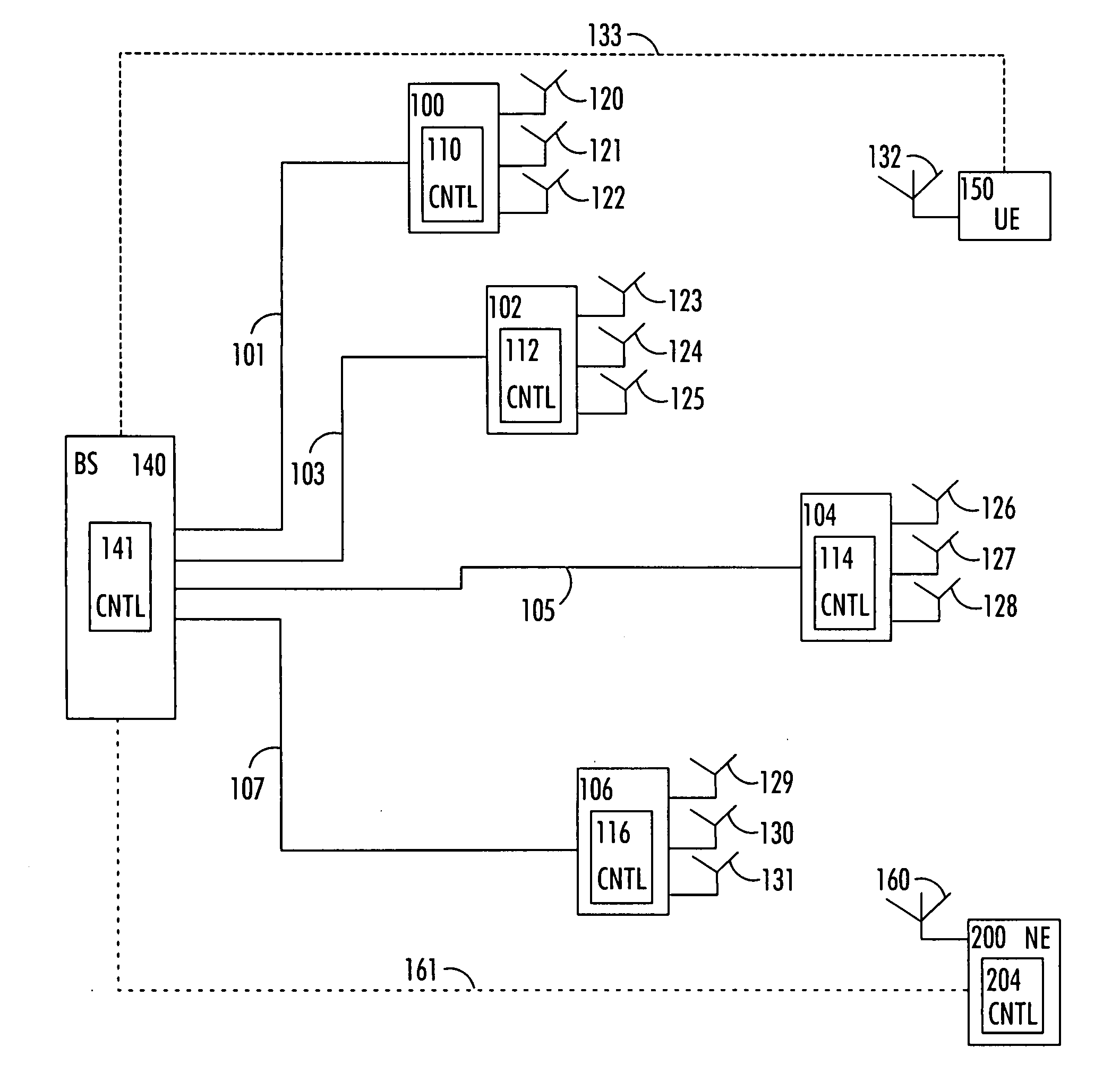
[0022]With reference to FIG. 1, let us examine an example of a distributed antenna system to which embodiments of the invention can be applied. The distributed antenna system has multiple antennas spatially distributed throughout each cell. In the example of FIG. 1, a common base station 140 communicates with a number of antenna units 100, 102, 104, 106 over communication links 101, 103, 105, 107 respectively. The communication links 101, 103, 105, 107 between the antenna units 100, 102, 104, 106 and the common base station 140 can be, e.g. wired or wireless, such as baseband (e.g. over optical fibre) or radio frequency (e.g. radio over fibre). Also a wireless link between the antenna units and the base station is possible. The system can be any distributed antenna system. In an embodiment, the distributed antenna system is a multiple-input multiple-output (MIMO) based 4G system.

[0023]Each of the antenna units 100, 102, 104, 106 comprises capability to transmit and receive informati...


PUM


Abstract

There is provided a method comprising: determining a phase difference between at least two antenna units of a distributed antenna system on the basis of at least one pilot signal received from at least one of a plurality of antenna units; and transmitting phase correction commands to a common base station of the plurality of antenna units on the basis of the determined phase difference in order to synchronize carrier phases between at least two antenna units of the distributed antenna system.

Description

FIELD [0001]The invention relates to a method, to a communication system, to a base station, to a user entity, to a network entity, and to a computer-readable program distribution medium.BACKGROUND [0002]Concepts based on multiple transmit and receive antennas are the most promising techniques for achieving high data rate communication. However, since the carrier frequencies are expected to grow in the future wireless communications systems (e.g. to 5 GHz for so called fourth generation), the path loss also increases and reduces the advantages offered by traditional multiple-input multiple-output (MIMO) system architecture.[0003]To overcome this loss, a new network architecture based on distributed antenna concept has been recently proposed. The key idea of this proposal, referred as distributed MIMO system, comprises distributing groups of antennas over a large geographical area. All the antenna groups are connected to a common base transceiver station (BTS) where the actual radio ...

Claims


Application Information

Patent Timeline
IPC IPC(8): H03D13/00
CPCH04B17/21H04B7/06H04B7/024H04B7/0617H04B7/0623H04B7/0671H04B7/0673
Inventor CODREANU, MARIANTOLLI, ANTTIJUNTTI, MARKKULATVA-AHO, MATTI
Owner WSOU INVESTMENTS LLC
Why Eureka
Try Eureka