Microscope generating a three-dimensional representation of an object and images generated by such a microscope

a three-dimensional representation and microscope technology, applied in the field of microscope generating a three-dimensional representation of observed objects, can solve the problems of inconvenient use of microscopes, inability to obtain images, and inability to use microscopes with extremely small index variations,

Inactive Publication Date: 2003-02-25
LAUER VINCENT
View PDF2 Cites 145 Cited by
  • Summary
  • Abstract
  • Description
  • Claims
  • Application Information

AI Technical Summary

Benefits of technology

Microscopes of the first category exhibit limitations in terms of observed image size, characteristics imposed on the object, or displayable parameters. These limitations are due to the fact that, in the absence of a reference wave distinct from the illuminating wave, it is not possible to acquire under good conditions the complex value of the wave received on the receiving surface. It is thus necessary to use various expedients to eliminate spurious images and various disturbances generated by the drawbacks of the acquisition method.

Problems solved by technology

This microscope is not very suitable for obtaining images that take into account the index of the sample.
The use of the [Noda] microscope is however limited to the study of non-absorbing objects whose index variations are extremely small.
Consequently, that microscope does not have means for varying the phase of the reference wave.
In the optics field, where wavelengths are sub-micrometric, this is difficult to achieve.
If this movement is significant, this effect destroys the image.
This condition is in principle difficult to obtain.
This solution is however not perfect, depending essentially on a visual interpretation.
However, the material configurations proposed do not allow the solution of the problem consisting in determining, to within a fraction of a wavelength, the position of the transmitter and the receiver in relation to the object.
In fact, the illuminating wave of variable direction is produced by mechanical devices which cannot be controlled with sub-micrometric accuracy.
The image obtained by [Lauer 1] is affected by a residual granularity effect, does not allow a differentiation of the refractive index and of absorptivity, and does not yield the theoretical accuracy indicated by [Wolf].

Method used


Image

  • Microscope generating a three-dimensional representation of an object and images generated by such a microscope
  • Microscope generating a three-dimensional representation of an object and images generated by such a microscope
  • Microscope generating a three-dimensional representation of an object and images generated by such a microscope

Examples


second embodiment

6. DESCRIPTION OF A SECOND EMBODIMENT

This embodiment is a simple variant of the first and is represented in FIG. 25.

6.1. Principle

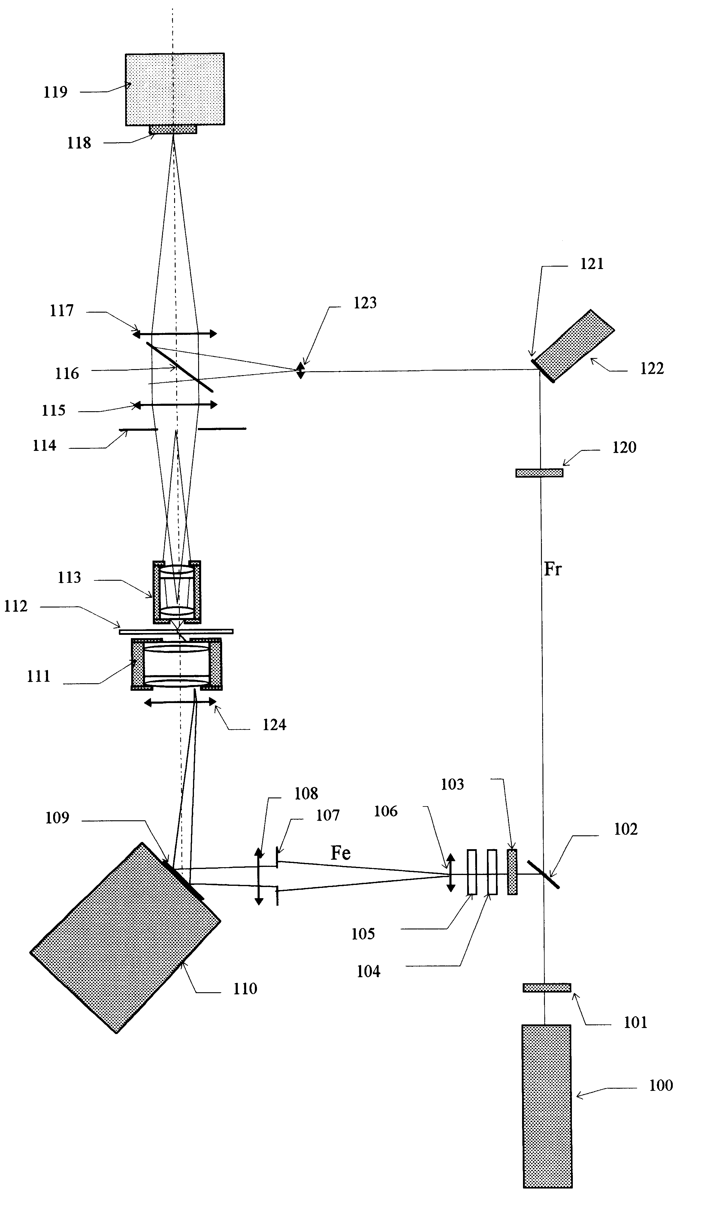
In the first embodiment, the sensor (118) is in the back (image) focal plane of the optical assembly made up of the objective (113) and lenses (115) and (117). The plane illuminating wave thus has a point image in this plane, and a spherical reference wave centered virtually on the object must be used to obtain homogeneous illumination on the sensor (118). In this second embodiment, the sensor (2018) is placed directly in the image plane of the objective. A plane illuminating wave consequently no longer has a point image. The reference wave must be the image through the objective of a virtual plane wave passing through the object.

first embodiment

An image in complex numbers is obtained on the CCD (2018) from three images differing in the phase of the reference wave, using, as in the first embodiment, the formula ##EQU62##

The two-dimensional Fourier transform of this image gives an image in complex numbers equivalent to that which, in the first embodiment, was obtained directly in the plane of the CCD sensor. This image thus replaces the image obtained directly on the sensor in the first embodiment. For the rest, this embodiment uses the same principles as the first.

6.2. Equipment description

The system is represented in FIG. 25. The elements of this figure, identical to those of FIG. 1, are numbered by replacing the first digit 1 of the elements of FIG. 1 by the digit 20. For example (116) becomes (2016). This system is similar to the one used in the first embodiment, except that:

The device for controlled attenuation of the beam, made up of the elements (104) and (105) is eliminated.

The CCD (2018) is placed in the plane in wh...

third embodiment

7. DESCRIPTION OF A THIRD EMBODIMENT

This embodiment is more complex and more costly than the preceding but allows higher performance in terms of definition and speed.

7.1. Principle

This acquisition method makes it possible to improve the performances of the first embodiment as follows:

Higher image acquisition speed:

In the first embodiment, this speed is limited by the mechanical movement of the stepping motors and the need to wait for the absorption of vibrations induced after each movement. The present embodiment allows the acceleration of this image acquisition by replacing this mechanical system by an optical beam deflection system based on liquid crystals and not inducing any mechanical displacements in the system.

Improved precision:

In the first embodiment, the precision is limited by the impossibility of adopting all the possible directions for the illuminating beam and by the fact that the reflected wave is not taken into account. The present embodiment uses a two-objective sys...


PUM


Abstract

A microscope is disclosed which determines a complex three-dimensional representation of an object based on a series of recordings of the light wave diffracted by the object, wherein the direction of the wave lighting of the object varies between two succesive recordings. The diffracted wave interferes with a reference wave on a receiving surface and a frequency representation of the diffracted wave is computed from interference patterns received on the receiving surface. A plurality of frequency representations of diffracted waves are then superimposed yielding a frequency representation of the object. The phase of each frequency representation of a diffracted wave is shifted in order to compensate for variations of the phase difference between the reference wave and the wave lighting of the object.

Description

1. BACKGROUND OF THE INVENTIONThis invention relates to a microscope generating a three-dimensional representation of the observed object, operating on a principle derived from "image formation by scattered field inversion", tomography and synthetic aperture systems.2. THE PRIOR ART2.1. References[Wolf]: Three-Dimensional Structure Determination of Semi-Transparent Object from Holographic Data, Emil Wolf, Optics Communications, Vol. 1, No. 4, p.153, October 1969.[Dandliker]: Reconstruction of the Three-Dimensional-Refractive Index from Scattered Waves, R. Dandliker, K. Weiss, Optics Communications, Vol. 1, No. p.323, February 1970.[Fercher]: Image Formation by Inversion of Scattered Field Data: Experiments and Computational Simulation. A. F. Fercher, H. Bartelt, H. Becker, E. Wiltschko, Applied Optics, Vol.18, No 14, p.2427, July 1979[Kawata]: Optical Microscope Tomography. I. Support Constraint, S. Kawata, O. Nakamnura & S. Minami, Journal of the Optical Society of America A, Vol. ...

Claims


Application Information

Patent Timeline
Patent Type & Authority Patents(United States)
IPC IPC(8): G02B21/00G03H1/00G03H1/04
CPCG03H1/0443G03H1/0866G03H1/0406G03H2226/13G03H2001/045G03H2001/0458G03H2222/36G03H2001/005
Inventor LAUER, VINCENT
Owner LAUER VINCENT
Why Eureka
Try Eureka