Endoscope with detachable sheath

a technology which is applied in the field of endoscope and sheath, can solve the problems of increasing the cost of endoscopic inspection, the sheath to be snagged, and the conventional sheath, which is relatively expensive, and achieves the effect of low cost and simple arrangemen

Inactive Publication Date: 2005-06-28
ASAHI KOGAKU KOGYO KK
View PDF21 Cites 87 Cited by
  • Summary
  • Abstract
  • Description
  • Claims
  • Application Information

AI Technical Summary

Benefits of technology

[0006]The present invention is advantageous in that it provides an endoscope with a detac

Problems solved by technology

The sheath is put on the inserting tube in a manner as above since a floating portion of the sheath may cause the sheath to be snagged and even torn on a body wall when the inserting tube is inserted into a human body

Method used


Image

  • Endoscope with detachable sheath
  • Endoscope with detachable sheath
  • Endoscope with detachable sheath

Examples


first embodiment

[0025

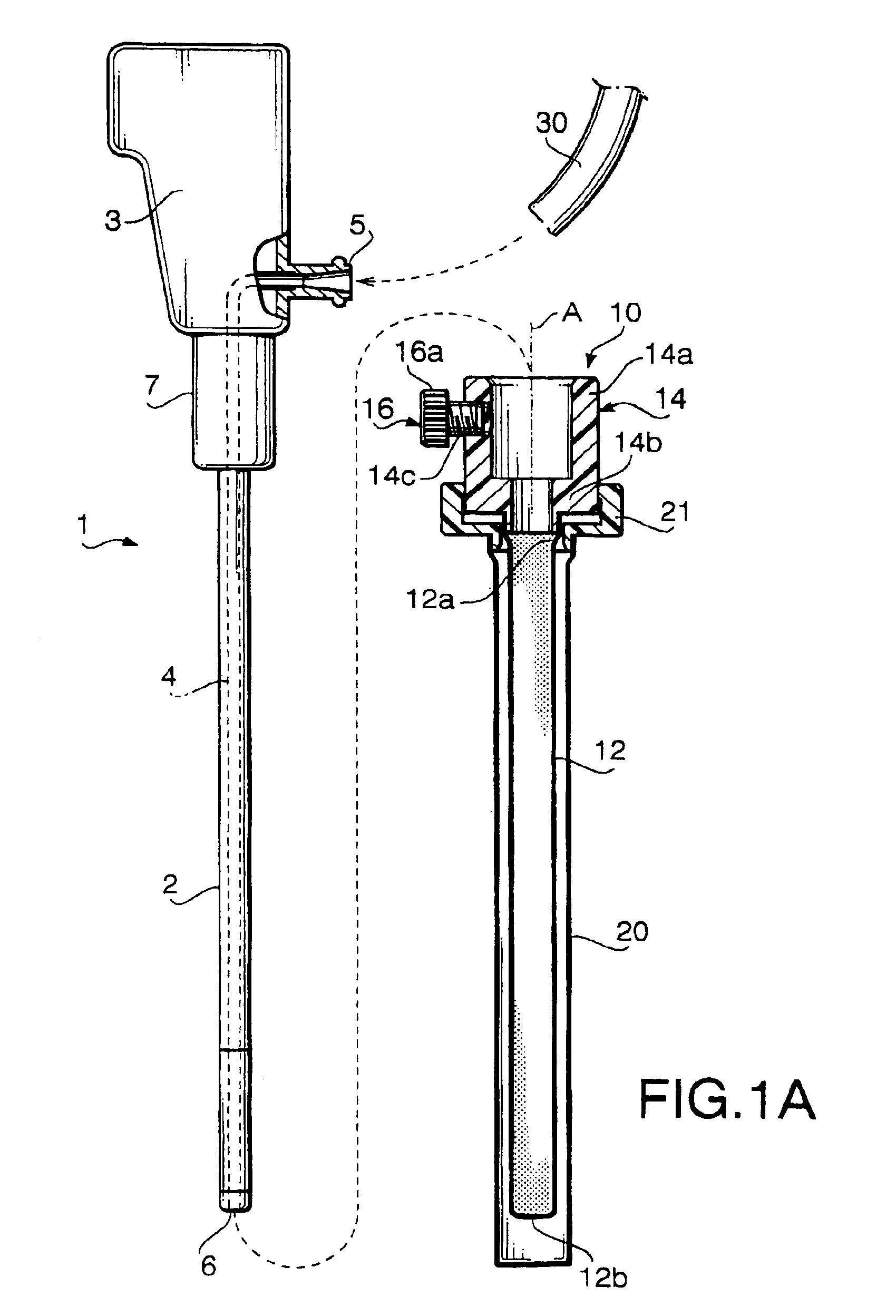
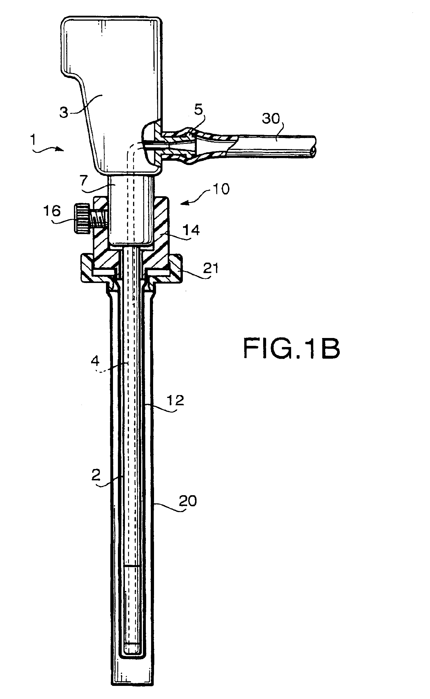
[0026]FIGS. 1A through 1C show an endoscope 1 with a detachable sheath 10 and a sheath cover 20 according to a first embodiment of the invention. In particular, FIG. 1A shows the endoscope 1 and the sheath 10 separately, and FIG. 1B the endoscope 1 covered with both the sheath 10 and the sheath cover 20, and FIG. 1C the endoscope 1 covered with the sheath 10 but the sheath cover 20 removed.

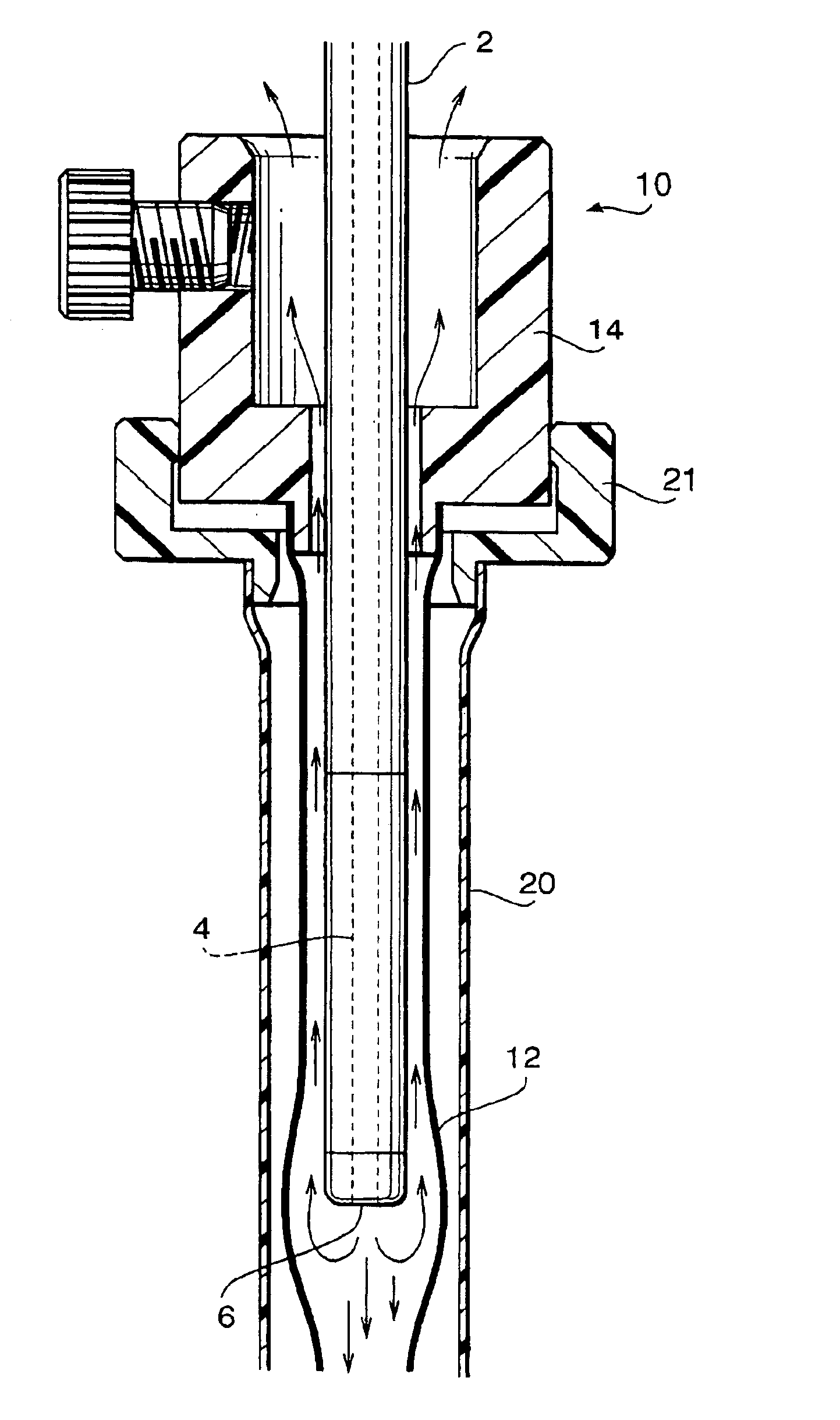
[0027]The endoscope 1 is provided with a flexible inserting tube 2 and an operation portion 3 connected to the proximal end of the inserting tube 2. The inserting tube side of the operation portion 3 is formed as an engaging portion 7 which engages with the proximal end of the sheath 10 when the inserting tube 2 is covered with the sheath 10 as will be described later. The engaging portion 7 is a cylindrical member having a substantially uniform outer diameter along its longitudinal direction.

[0028]The endoscope 1 is also provided with an air feeding tube 4 which extends throughout the insert...

second embodiment

[0049

[0050]FIGS. 3A and 3B show an endoscope 110 with a detachable sheath 120 according to a second embodiment of the invention. In particular, FIG. 3A shows the endoscope 110 and the sheath 120 separately, and FIG. 3B shows the endoscope 110 covered with the sheath 120.

[0051]The endoscope 110 includes an inserting tube 111 that is to be inserted into a human body, and an operation portion 112 connected to the proximal end of the inserting tube 112. The inserting tube 111 includes a flexible tube 111a having a bending portion 111b at the distal end side thereof. The bending portion 111b is part of the inserting tube 111 of which bending can be remotely controlled from the operation portion 112. A tip body 111c, which is provided with an observation window 116 and an illumination window 117, is mounted to the tip end of the bending portion 111b.

[0052]A sheath engaging portion 113 is formed at the lower end of the operation portion 112, or at the portion the inserting tube 111 is con...


PUM


Abstract

Combination of an endoscope and a sheath for covering an inserting tube of the endoscope, the sheath includes an elastic tubular member having an open proximal end and a closed distal end, and the endoscope is provided with an air feeding tube for feeding air from a distal end of the inserting tube to inflate the tubular member when the inserting tube is inserted into the tubular member to be covered therewith.

Description

BACKGROUND OF THE INVENTION[0001]The present invention relates to an endoscope and a sheath which detachably covers an inserting tube of the endoscope.[0002]Conventionally, the inserting tube of an endoscope is covered with a detachable sheath that is exchanged and discarded after each endoscopic inspection in order to prevent infection between patients via the endoscope.[0003]The sheath includes an elastic tubular portion for covering the inserting tube and a cylindrical supporting portion connected to the proximal end of the tubular portion so as to allow the inserting tube to be inserted into the tubular portion through the supporting portion. The supporting portion is provided with an air feeding conduit for feeding air into and thereby inflating the tubular portion, and a packing for sealing a gap around the inserting tube being passed therethrough to prevent leaking of the air fed into the tubular portion.[0004]The tubular portion is formed to have an inner diameter smaller th...

Claims


Application Information

Patent Timeline
IPC IPC(8): A61B1/00
CPCA61B1/00142
Inventor OUCHI, TERUOYAMAMOTO, KAZUYUKI
Owner ASAHI KOGAKU KOGYO KK
Why Eureka
Try Eureka