Spindle motor

a spindle motor and spindle technology, applied in the field of spindle motors, can solve the problems of difficult to accurately ascertain difficult to control the injection amount of fluid, and difficult to observe the interface of fluid with the naked eye, so as to achieve easy and intuitive control of the interface

Inactive Publication Date: 2010-08-19
SAMSUNG ELECTRO MECHANICS CO LTD
View PDF13 Cites 77 Cited by
  • Summary
  • Abstract
  • Description
  • Claims
  • Application Information

AI Technical Summary

Benefits of technology

[0021]The present invention has been made in an effort to provide a spindle motor, which uses a dual cap including an inner cap and a transparent outer cap. An upper thrust bearing and a first fluid sealing part are provided between the inner cap and a thrust plate, and a second fluid sealing part is provided between the inner cap and the outer cap. The dual cap allows the spindle motor to store more fluid therein. Further, while fluid is injected or the spindle motor is used, it is possible to more easily and intuitively control the interface of the fluid.

Problems solved by technology

However, the conventional spindle motor having the above construction is problematic in that, when the stopper 70 is installed to the sleeve 20 and thereafter fluid is injected, it is very difficult to control the injected amount of the fluid.
That is, it is impossible to observe the interface of the fluid with the naked eye, so that it is difficult to accurately ascertain the injected amount of the fluid.
Further, the conventional spindle motor is problematic in that it is impossible to intuitively see the lack of fluid resulting from the evaporation or scattering of the fluid while the spindle motor into which the fluid is injected is used, so that the rotating shaft may vibrate or malfunction because of the lack of the fluid.

Method used


Image

  • Spindle motor
  • Spindle motor
  • Spindle motor

Examples


Embodiment Construction

[0037]Hereinafter, a spindle motor according to the preferred embodiment of the present invention will be described in detail with reference to the accompanying drawings.

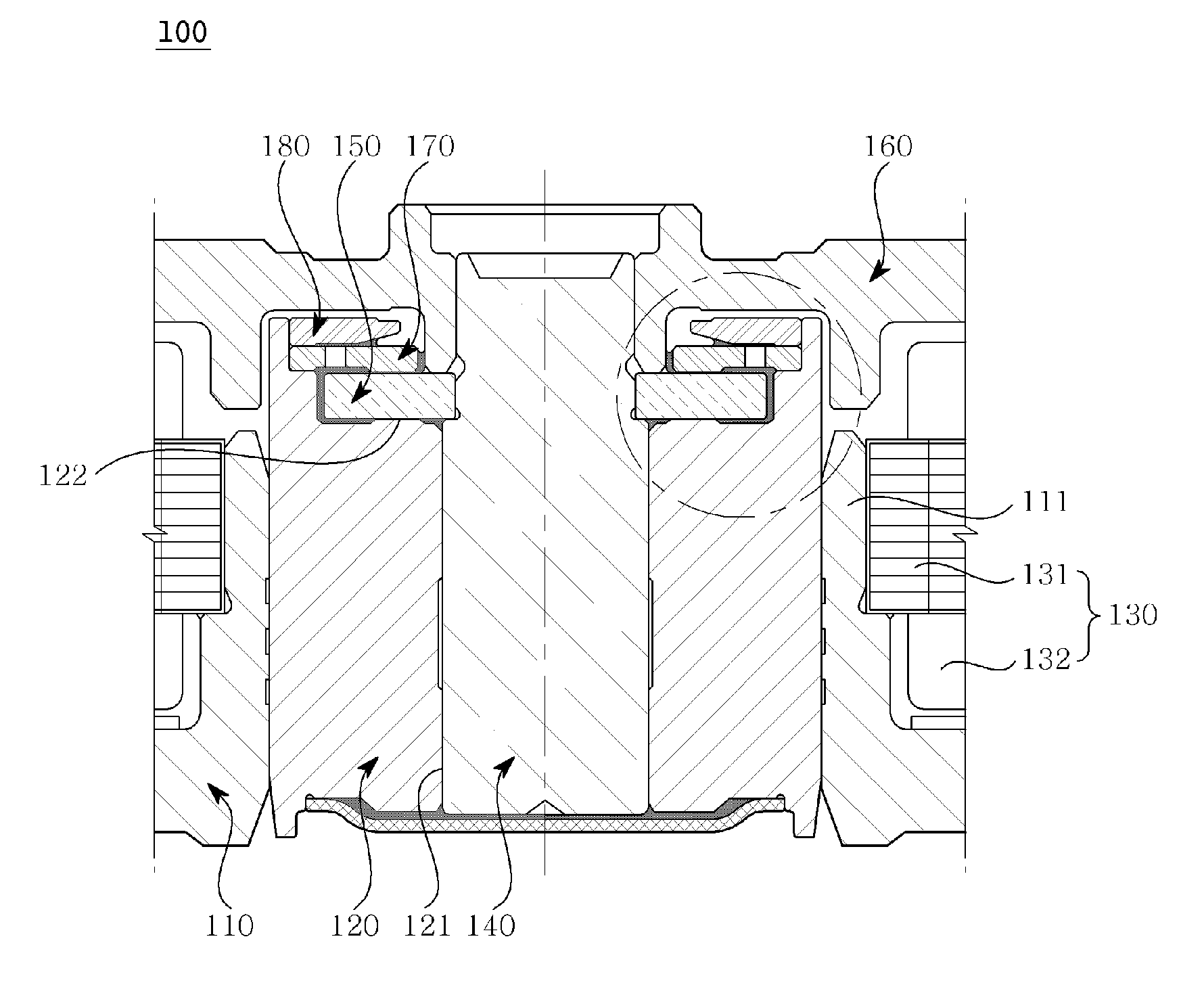
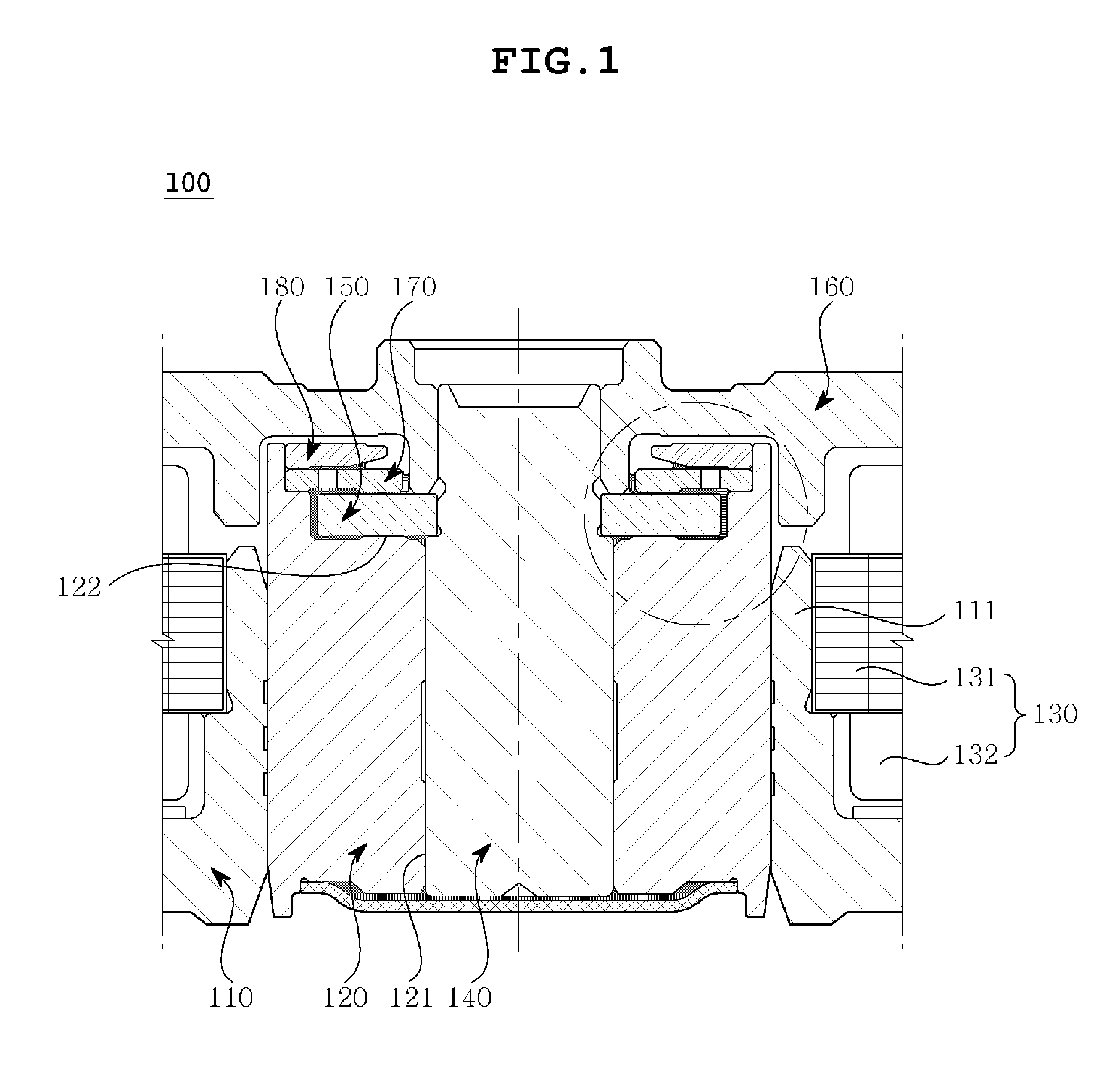
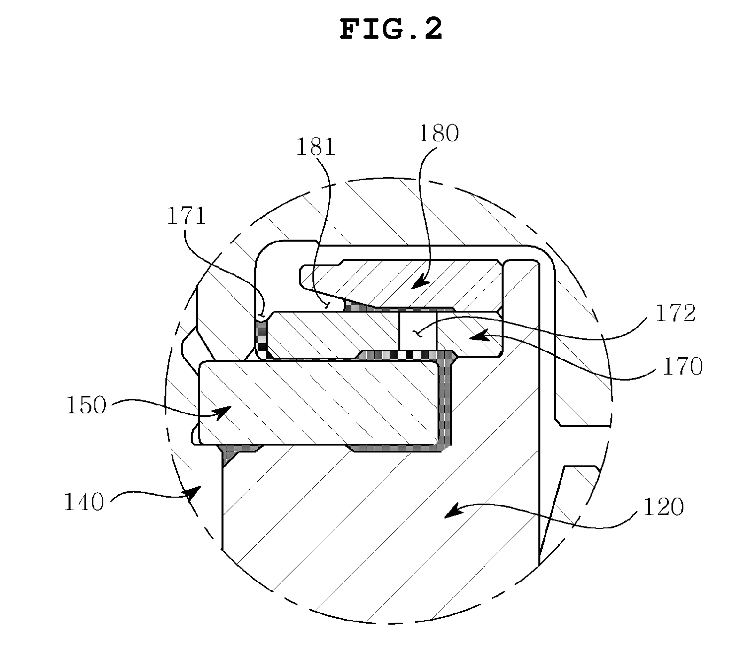
[0038]As shown in FIG. 1, a spindle motor 100 according to the preferred embodiment of the present invention includes a plate 110, a sleeve 120, an armature 130, a rotating shaft 140, a thrust plate 150, a hub 160, an inner cap 170 and an outer cap 180.

[0039]The plate 110 functions to support the entire spindle motor 100 and is mounted to a device such as a hard disk drive to which the spindle motor 100 is to be installed. Here, the plate 110 is manufactured out of a light material such as an aluminum plate or aluminum alloy plate. However, the plate 110 may be manufactured out of a steel plate.

[0040]Further, a coupling part 111 protrudes from the plate 110 in a cylindrical shape, so that the sleeve 120 is coupled to the coupling part 111. The coupling part 111 has in a central portion thereof a coupling hole having...


PUM


Abstract

Disclosed herein is a spindle motor including a journal bearing and a thrust bearing, thus preventing the lack of fluid occurring as a result of the evaporation or scattering of fluid, and making it easy to control the injected amount of fluid. The spindle motor includes a rotating shaft having a thrust plate inserted perpendicularly into the upper portion thereof. A sleeve accommodates and rotatably supports the rotating shaft. A plate is provided such that the sleeve is secured to the plate. An inner cap is secured to the sleeve in such a way as to face the upper surface of the thrust plate, and a first fluid sealing part is defined between the thrust plate and the inner cap. An outer cap is secured to the upper portion of the inner cap, and a second fluid sealing part is defined between the inner and outer caps.

Description

CROSS REFERENCE TO RELATED APPLICATION(S)[0001]This application claims the benefit of Korean Patent Application No. 10-2009-0012099, filed on Feb. 13, 2009, entitled “Spindle Motof”, which is hereby incorporated by reference in its entirety into this application.BACKGROUND OF THE INVENTION[0002]1. Field of the Invention[0003]The present invention relates generally to a spindle motor and, more particularly, to a spindle motor which includes hydrodynamic bearings comprising a journal bearing and a thrust bearing, thus preventing the lack of fluid occurring as a result of the evaporation or scattering of fluid, and making it easy to control the injected amount of fluid.[0004]2. Description of the Related Art[0005]Generally, a spindle motor maintains high precision rotational characteristics, because a bearing housing a rotating shaft therein rotatably supports the rotating shaft. Because of these characteristics, the spindle motor has been widely used as the drive means of hard-disk dr...

Claims


Application Information

Patent Timeline
Patent Type & Authority Applications(United States)
IPC IPC(8): H02K7/08
CPCF16C17/045F16C2370/12G11B19/2036F16C33/745H02K5/15H02K5/16H02K29/00
Inventor KIM, JIN SANLEE, KUM KYUNG
Owner SAMSUNG ELECTRO MECHANICS CO LTD
Why Eureka
Try Eureka