Air bag and air bag device

Inactive Publication Date: 2010-08-26
HONDA MOTOR CO LTD +1
View PDF17 Cites 20 Cited by
  • Summary
  • Abstract
  • Description
  • Claims
  • Application Information

AI Technical Summary

Benefits of technology

[0021]According to the airbag of the first aspect, when gas is introduced into a gas introducing portion in a retracted and accommodated state, a second bag inflates and expands and a first bag inflates and expands with gas being supplied from the second bag thereto via the gas distributing portion. In a process in which the airbag inflates and expands, an outside top face portion and an inside top face portion, jointed with each other by means of a jointing portion, expand integrally toward a target to be protected in a sheet-like manner. In addition, in the process in which the airbag inflates and expands, in a case where the target to be protected is spaced from a sheet-like jointed portion, the jointing portion breaks away owing to a pressure of the gas supplied into the first bag, i.e., between the first bag and the second bag. Afterwards, the outside top face portion and the inside top face portion are separated from each other; the first bag further inflates and expands so as to allow the outside top face portion to be proximal to the target to be protected, enabling the airbag to appropriately protect the target to be protected. On the other hand, while the target to be protected is in abutment against the sheet-like jointed portion by the jointing portion, it is compressed in a direction in which the outside and inside top face portions are brought into intimate contact with each other; the jointing portion is reinforced; and breaka

Problems solved by technology

As described above, the conventional construction entails the problem that its

Method used


Image

  • Air bag and air bag device
  • Air bag and air bag device
  • Air bag and air bag device

Examples


Example

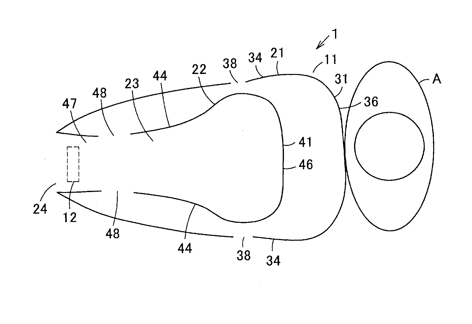
[0031]Hereinafter, one embodiment of an airbag and an airbag device, according to the present invention, will be described referring to the drawings.

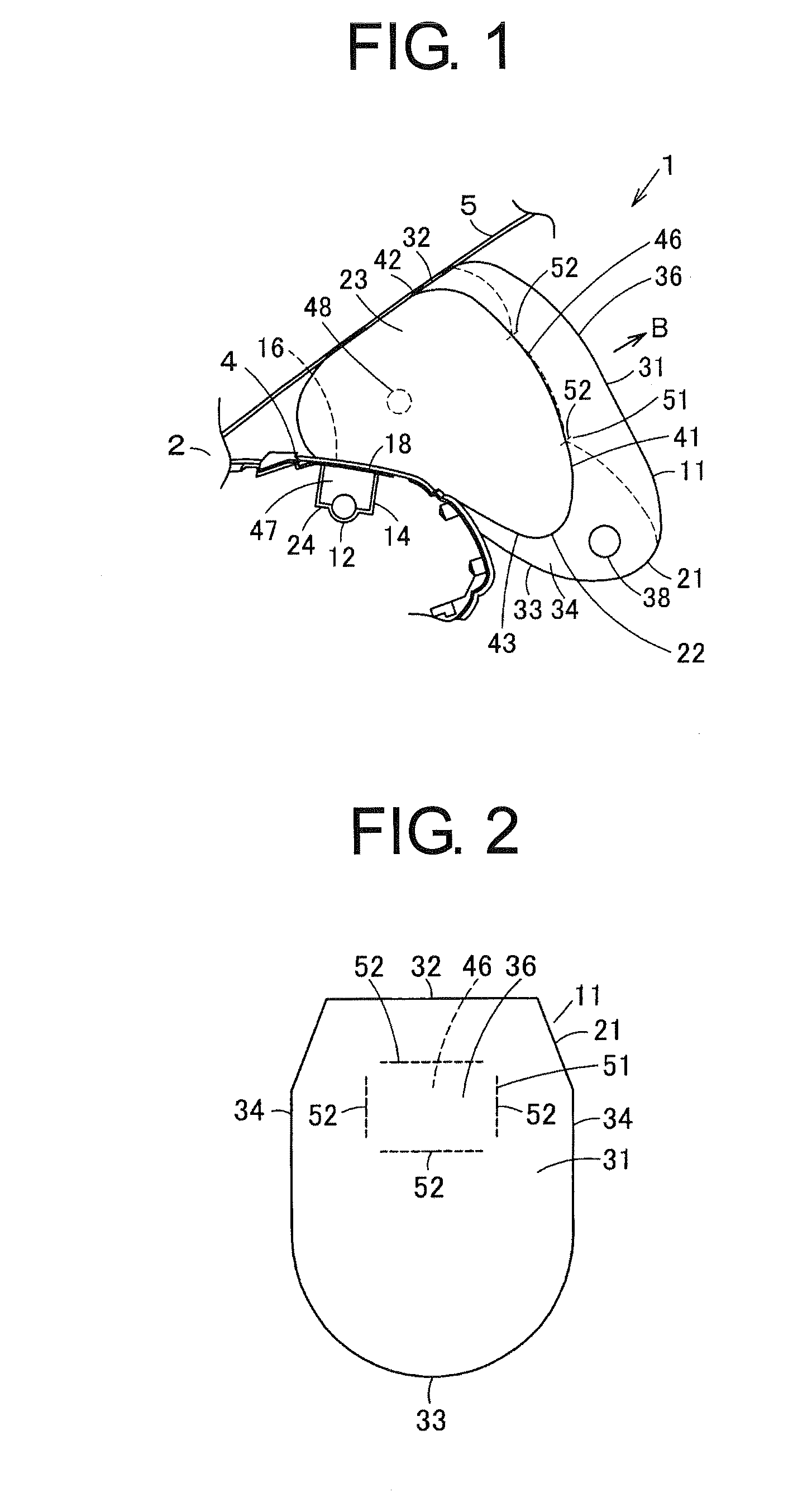
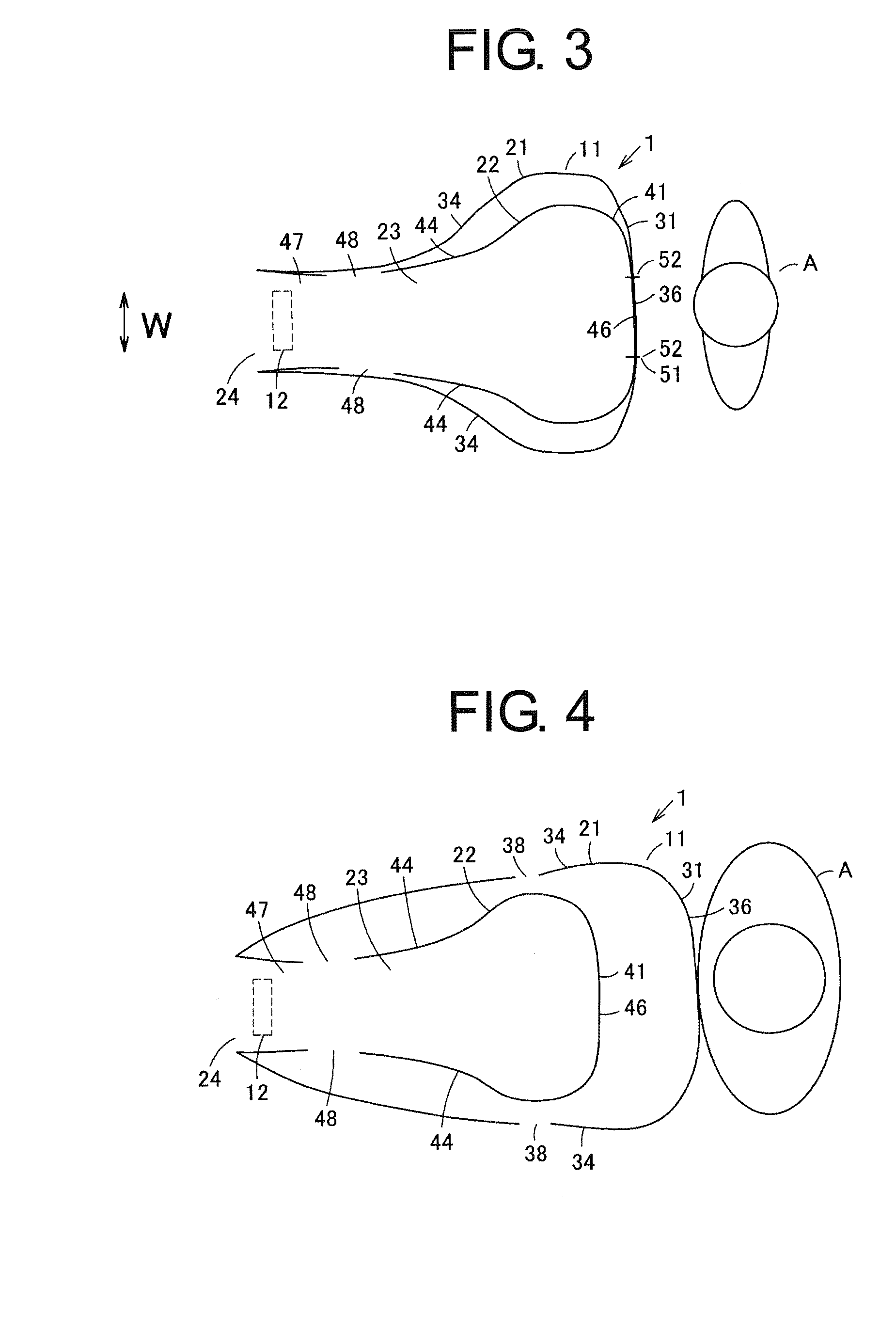
[0032]In FIGS. 1, 3, and 5, reference numeral 1 designates an airbag device. This airbag device 1 is disposed at a passenger's seat of an automobile 2 as a vehicle which is a movable body, i.e., inside of an instrument panel portion 4 as an installation portion positioned in front of an occupant A at the passenger's seat, which is a target to be protected; and constitutes an airbag device 1 for occupant at passenger's seat. In the following description, a longitudinal direction, a transverse direction, and a vertical direction are explained with reference to an automobile cruising direction with the airbag device 1 being mounted on the automobile, and the transverse direction corresponds to a vehicle widthwise direction (W direction indicated by the arrow shown in FIG. 3). The instrument panel portion 4 is formed at a site shaped like a...


PUM


Abstract

An airbag and an airbag device, which are capable of readily improving expansion characteristics of the airbag and reducing manufacturing cost, are provided. An airbag 11 for occupant at passenger's seat includes a first bag 21 and a second bag 22 which is provided inside of the first bag 21. An outside top face portion 36 of the first bag 21 and an inside top face portion 46 of the second bag 22 are brought into a sheet-like intimate contact with each other, and are detachably jointed at the jointing portion 51. The jointing portion 51 is comprised of a breakable seam line 52. Gas is supplied into the second bag 22 to thereby expand the first bag 22, and is supplied into the first bag 21 via a gas distributing portion 48 to thereby expand the first bag 21. In a case where an occupant exists at a predetermined position, the jointing portion 51 breaks away, and the first bag 21 then expands to its maximum. In an OOP state in which the occupant exists in the proximity of the airbag device 1, a head part of the occupant holds the outside top face portion 36 and disallows breakage of the jointing portion 51, so that expansion of the first bag 21 to the occupant side can be restrained and the occupant can be protected with an appropriate force.

Description

CROSS REFERENCE TO RELATED APPLICATIONS[0001]This application claims priority of Japanese Patent Application No. 2009-044117 filed on Feb. 26, 2009. The contents of this application are incorporated herein by reference in their entirety.BACKGROUND OF THE INVENTION[0002]1. Field of the Invention[0003]The present invention relates to an airbag and an airbag device for occupant at passenger's seat, which are included in an instrument panel of a vehicle, for example.[0004]2. Description of the Related Art[0005]Conventionally, an airbag device for occupant at passenger's seat is employed for protecting an occupant at passenger's seat of a vehicle. This airbag device is included in an instrument panel which is opposed to the occupant at the passenger's seat, and is provided with constituent elements such as: a case member substantially shaped like a case; an airbag substantially shaped like a bag, which is retracted and accommodated in this case member; an inflator which is mounted on the...

Claims


Application Information

Patent Timeline
IPC IPC(8): B60R21/233B60R21/16
CPCB60R2021/23332B60R21/2346
Inventor NAGAI, MAKOTOBARASAWA, AKIHIROSAGISAKA, RYUJI
Owner HONDA MOTOR CO LTD
Why Eureka
Try Eureka