Garment ventilation structure

a ventilation structure and garment technology, applied in the field of garments, can solve the problems of poor cooling, perspiration and discomfort of shirt wearers anywhere on the body, and achieve the effect of improving wearer comfor

Inactive Publication Date: 2010-09-02
MESSIOU ANTOINE YVON
View PDF4 Cites 10 Cited by
  • Summary
  • Abstract
  • Description
  • Claims
  • Application Information

AI Technical Summary

Benefits of technology

[0006]Unlike traditional sports shirts, the present invention is directed to improve wearer comfort by providing novel air channels for ventilation at selected points around the wearer's torso. Other structures may be provided in conjunction with the ventilation channels. Unlike a shirt that might provide ventilation by simple open holes or a large mesh, the channel openings in the present invention are concealed, thus protecting the wearer from sunlight and harmful U.V. radiation. It may also be desirable for aesthetic reasons to conceal the holes in the garment. Improved fabrication techniques, which exploit the thermoplastic nature of synthetic fabrics are also employed. It is well known that thermographic analysis of the human body shows that strenuous activity generates localised heat build-up around the chest and back as well as the upper arm. The thermal profile will naturally vary depending on many factors such as body size and the type of activity. Generally, the heart and main upper body muscles are the major areas of heat generation. Such heat generation induces perspiration in the body, causing the shirt wearer discomfort. Perspiration and discomfort can occur anywhere on the body if covered by a heavy or insulating layer.
[0007]The present invention is intended to improve heat dissipation and reduce perspiration, at selected areas by improved ventilation. The provision of ventilation by near vertical air columns, guided by the channels, works with the natural direction of heat convection and serves to improve wearer comfort. For an effective channel depth D, the actual channel depth, for a channel width w must be D+d where d can calculated approximately from the formula d=w2 / 8 r, where r is the minimum localised body radius in a horizontal plane. In one embodiment, ventilation at the front and rear of the torso is provided by four vertical channels in total. In another embodiment, multiple channels in close proximity provide ventilation. Embodiments with non-vertical channels, are also described for application when, for instance, body shape or aesthetics impose design constraints. It is not necessary to improve ventilation at all points within the torso to afford improvement in wearer comfort and coolness. High performance synthetic fabric with known advantages is used as the main shirt material within the invention.
[0008]In another embodiment of the invention, the ventilation channels are provided with active ventilation structures within the channels. This embodiment is directed to further improve wearer comfort and is again provided at selected points on the wearer's body. Protective apparel in many cases encases the body in a heavy or insulating material, thus making better ventilation even more desirable. This embodiment continues to provide ventilation benefits even if covered with another layer, provided the channel openings are unobstructed. This is in contrast to a traditional shirt or garment, which, even if made from high performance moisture transport fabrics, results in poor cooling as the high performance fabric benefits are limited if covered by another garment layer.

Problems solved by technology

Such heat generation induces perspiration in the body, causing the shirt wearer discomfort.
Perspiration and discomfort can occur anywhere on the body if covered by a heavy or insulating layer.
This is in contrast to a traditional shirt or garment, which, even if made from high performance moisture transport fabrics, results in poor cooling as the high performance fabric benefits are limited if covered by another garment layer.

Method used


Image

  • Garment ventilation structure
  • Garment ventilation structure
  • Garment ventilation structure

Examples


Embodiment Construction

[0049]Repeated use of reference numbers in the present specification and drawings is intended to represent the same or analogous features of the invention.

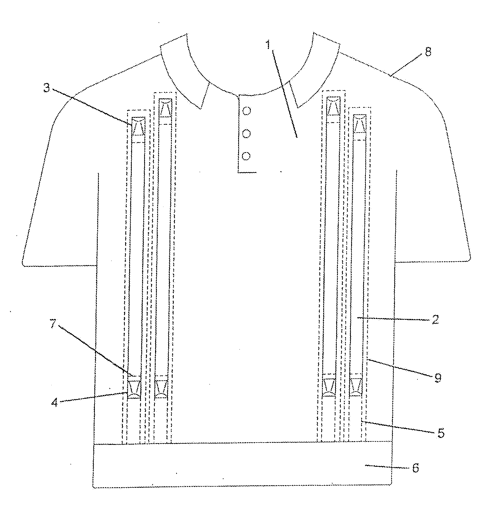
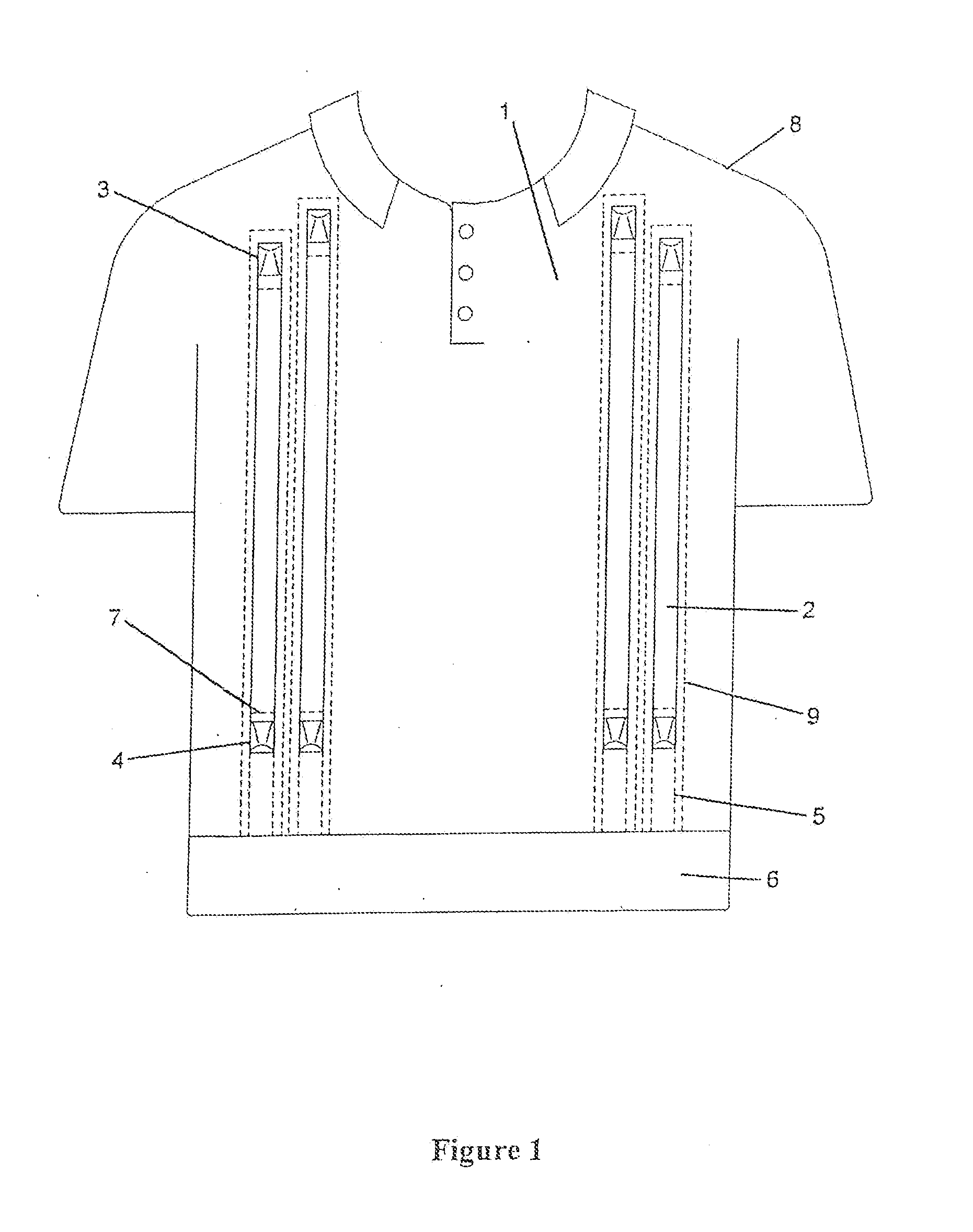
[0050]It is to be understood that to one skilled in the art that the following is a description of the exemplary embodiments only and is not intended as limiting the broader aspects of the present invention, which broader aspects are embodied in the exemplary fabrication. For illustrative and descriptive clarity only key items are included in the drawings. Details of trim and extraneous flanges for attachment to the apparel itself are shown only where necessary for clarity.

[0051]The present invention is directed to sports shirts fabricated with integral ventilation channels. Referring to FIG. 1, a sports shirt 1, is shown with integral ventilation channels 2, upper opening eyelet 3 and lower opening eyelet 4. For the purposes of descriptive clarity, only the front view of the sports shirt is shown and similar channels can be assum...


PUM


Abstract

A garment such as a sports shirt has concealed ventilation channels, which provide a continuous air channel between permanent openings. In one embodiment, the channels are flexible and non-intrusive and the openings are maintained by springy eyelets. The eyelets and channels are attached to the main fabric of the garment, providing a robust and a streamlined construction. Another embodiment incorporates active ventilation structures within the channels, the structures having a natural vibration frequency matched to a motion frequency spectrum of the wearer. In a further embodiment, the ventilation channels are made of shape memory polymer and change shape in response to changes in temperature.

Description

CROSS-REFERENCE TO RELATED PATENT APPLICATIONS[0001]This patent application is a continuation of U.S. patent application Ser. No. 10 / 514,210 filed Apr. 26, 2005, which claims the benefit of PCT / GB2003 / 002019 filed May 12, 2003 designating the United States, and claims priority from United Kingdom Patent Application 0210733.2 filed May 10, 2002 and from United Kingdom Patent Application 0215729.5 filed Jul. 6, 2002. The teachings and disclosures of all those applications are hereby incorporated in their entireties by reference thereto.FIELD OF THE INVENTION[0002]This invention relates to garments including leisure apparel, and more particularly to sports shirts.BACKGROUND OF THE INVENTION[0003]In many activities, where sports and leisure apparel is worn, there is a demand for lightweight apparel, which is cool and comfortable, and has other desirable properties including moisture and perspiration transmission away from the wearer. In addition, fabrics and shirts with good wear charac...

Claims


Application Information

Patent Timeline
Patent Type & Authority Applications(United States)
IPC IPC(8): A41B1/00A41D27/00A41D27/28A43B7/06
CPCA41D27/28C08L2201/12A43B7/06A43B3/00A41D27/285
Inventor MESSIOU, ANTOINE YVON
Owner MESSIOU ANTOINE YVON
Why Eureka
Try Eureka