System for supporting and servicing a gas turbine engine

Active Publication Date: 2010-09-02
SOLAR TURBINES
View PDF35 Cites 137 Cited by
  • Summary
  • Abstract
  • Description
  • Claims
  • Application Information

AI Technical Summary

Problems solved by technology

The system and method of the '442 patent may allow for horizontal installation of a section of a gas turbine engine, but fails to permit horizontal movement in a direction substantially parallel to the drive axis of the GTE between two stationary sections of the GTE.
The system of the '442 patent is inefficient because sections of the GTE are installed sequentially

Method used


Image

  • System for supporting and servicing a gas turbine engine
  • System for supporting and servicing a gas turbine engine
  • System for supporting and servicing a gas turbine engine

Examples


first embodiment

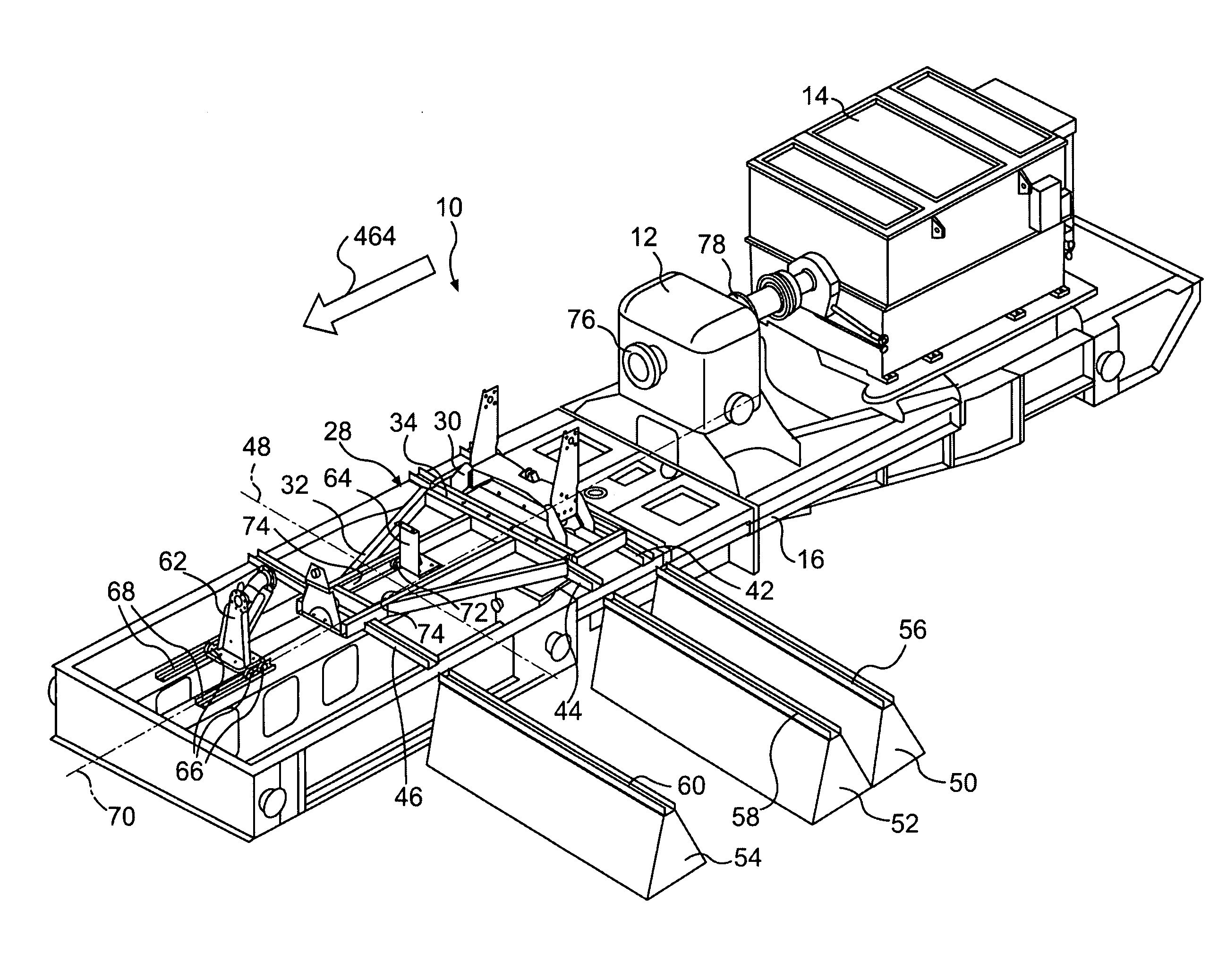
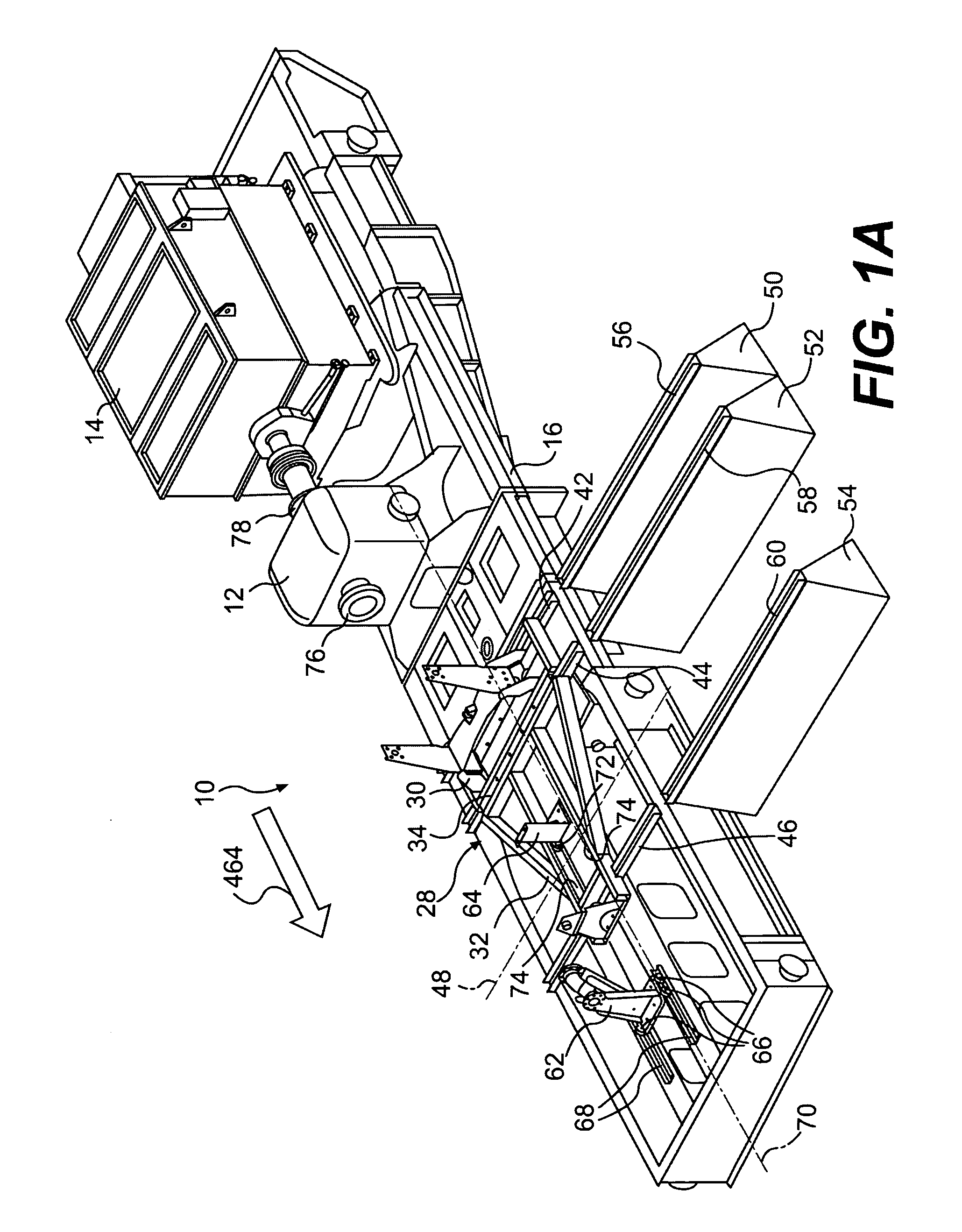
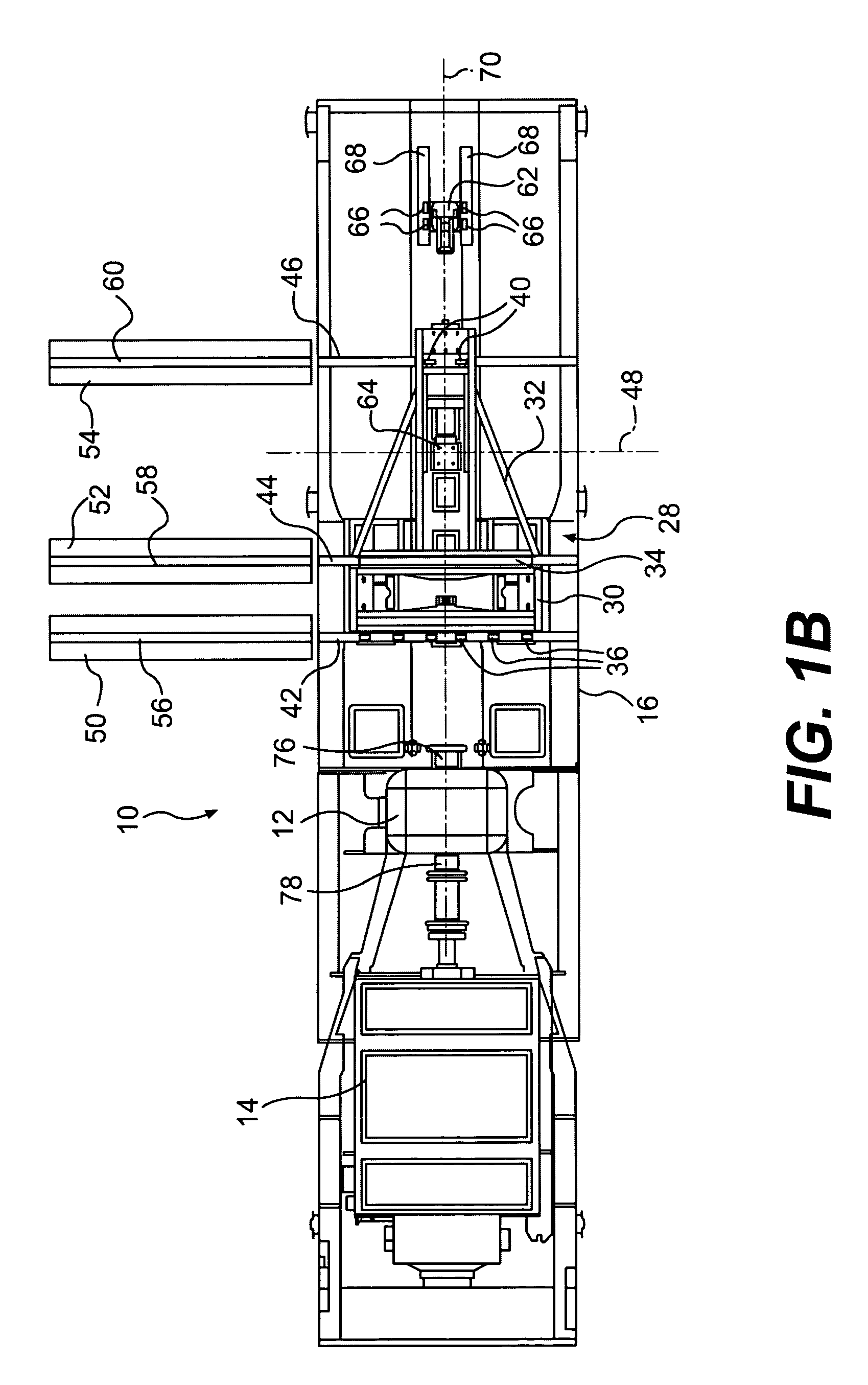
[0046]FIGS. 1A-1D illustrate a support system 10 for a power system having a gas turbine engine (not shown in FIGS. 1A-1D), support system 10 having a power-transfer unit 12 and a power load 14 mounted thereon. Support system 10 may include a base / support 16 that supports power-transfer unit 12 and power load 14. For example, as FIGS. 1A-1D show, base / support 16 may be a frame. Base / support 16 may be supported by various entities, including, but not limited to, the ground (not shown), one or more structures supported by the ground (not shown), one or more structures of a vehicle (not shown), and / or one or more structures of a marine vessel (not shown).

[0047]Support system 10 may include various provisions for supporting a gas turbine engine (not shown). For example, support system 10 may include a frame 28 for supporting a gas turbine engine from base / support 16. Frame 28 may include a support 30 and a support 32 disposed adjacent to one another. Support 30 and support 32 may includ...

second embodiment

[0058]FIGS. 6A, 6B, 7A-7F, 8A-8C, 9, 10A-10D, 11, 12A, 12B, 13, and 14A-C show various states of assembly of a support system 110 and a power system 180 that includes support system 110 and a gas turbine engine 182. FIGS. 6A and 6B show a base / support 116 of support system 110. Base / support 116 may be a frame. Base / support 116 may be supported by various entities, including, but not limited to, the ground (not shown), one or more structures supported by the ground (not shown), one or more structures of a vehicle (not shown), and / or one or more structures of a marine vessel (not shown).

[0059]FIGS. 7A-7F show gas turbine engine 182 mounted to base / support 116. FIGS. 7A and 7B provide perspective views of gas turbine engine 182 and base / support 116 from opposite sides; FIG. 7C provides an elevational view of gas turbine engine 182 and base / support 116; FIG. 7D provides a plan view of gas turbine engine 182 and base / support 116; FIG. 7E provides an enlarged view of the portion of FIG. 7...


PUM


Abstract

A power system includes a gas turbine engine, which may include a gear box. The gear box may include a pipe connection configured to receive a removable pipe. The power system may also include a moveable support configured to fasten to the pipe connection to at least partially support the gear box.

Description

[0001]This application claims the benefit of priority under 35 U.S.C. §119(e) of U.S. Provisional Application No. 61 / 193,787, filed Dec. 23, 2008. This application is also a continuation-in-part of U.S. patent application Ser. No. 12 / 003,665, filed Dec. 23, 2008, of Ian Trevor Brown, Daniel James Doll, and Jason Michael Robertson, and is a continuation-in-part of U.S. patent application Ser. No. 11 / 477,373, of Ian Trevor Brown and Daniel James Doll, filed Jun. 30, 2006, and entitled “Power System.” Provisional Application No. 61 / 193,787, application Ser. No. 12 / 003,665, and application Ser. No. 11 / 477,373 are incorporated herein by reference in their entirety.TECHNICAL FIELD[0002]The present disclosure relates to gas turbine engine power systems and, more particularly, to systems and methods for servicing such systems.BACKGROUND [0003]Many power systems include a gas turbine engine and a power load, such as a pump, compressor, or electric generator, drivingly connected to the gas tu...

Claims


Application Information

Patent Timeline
IPC IPC(8): F02C7/20B23P6/00
CPCY10T29/49721F16M5/00Y10T29/53548F05D2230/68Y10T29/4973Y10T29/49998Y10T29/49318F16M1/04F05D2250/313Y10T29/49895F01D25/285F05D2230/70Y10T29/53961F05D2230/60
Inventor BROWN, IAN TREVORDOLL, DANIEL JAMESROBERTSON, JASON MICHAELSMITH, DANNY FERREL
Owner SOLAR TURBINES
Why Eureka
Try Eureka