
Portable watch

Active Publication Date: 2010-09-02
SEIKO INSTR INC
View PDF12 Cites 34 Cited by
  • Summary
  • Abstract
  • Description
  • Claims
  • Application Information

AI Technical Summary

Benefits of technology

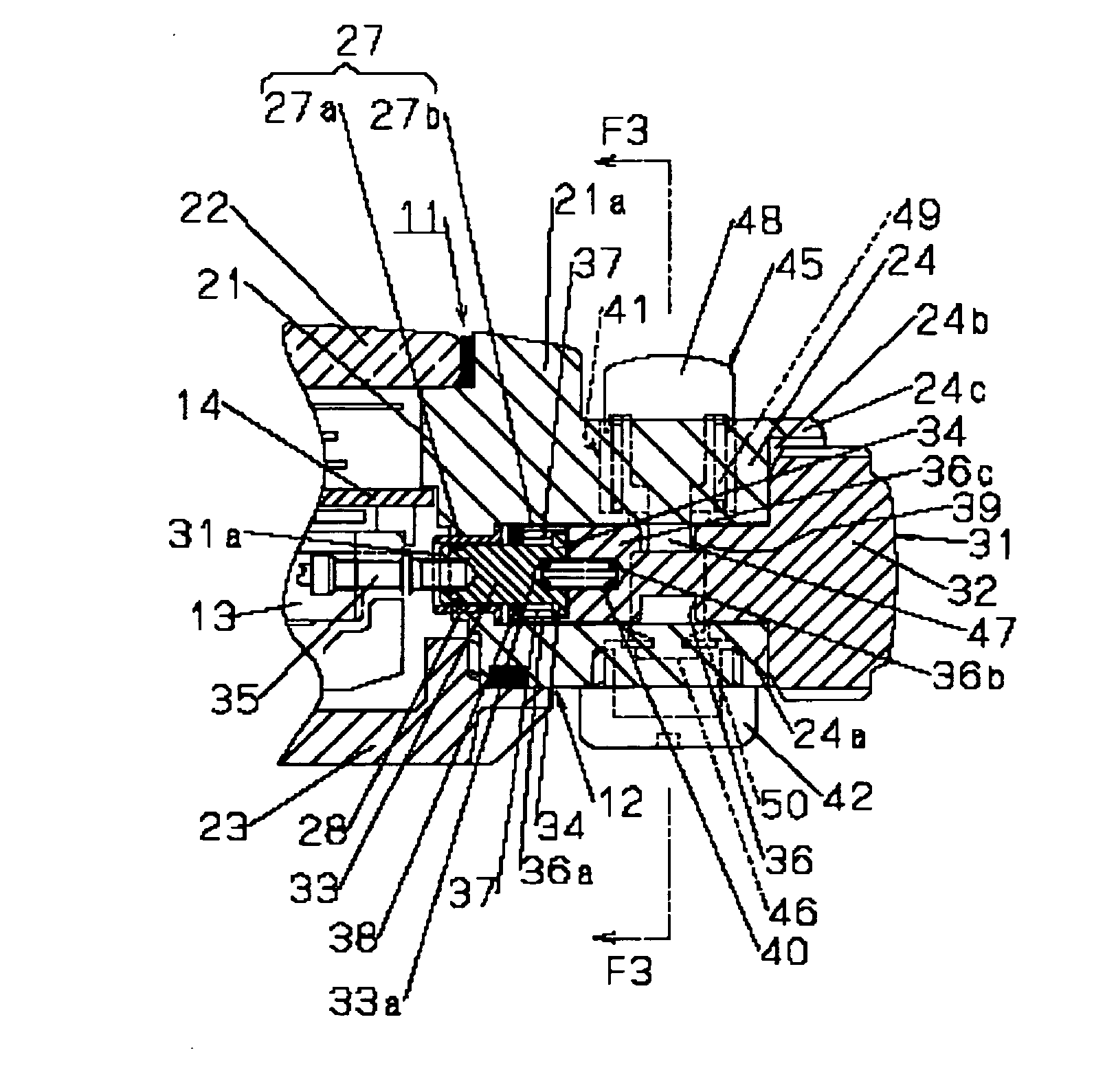
[0011]In the portable watch of the present invention, the crown lock member is arranged at a lock position by the urging force of the urging member, and this lock member is retained in a state in which it is engaged with the lock groove of the crown. Thus, even if, while the portable watch is being carried about, there is applied a force directed to the case band exterior side of the crown, the crown is not erroneously pulled out, and, consequently, it is possible to prevent erroneous rotation of the crown.
[0033]In the portable watch of the present invention, it is possible to achieve an improvement in terms of operability in performing the operation of preventing an erroneous operation of the crown and in enabling the operation of the crown.

Problems solved by technology

In the prior-art technique disclosed in Patent Document 1, in both preventing an erroneous operation of the crown and enabling the operation of the crown, it is necessary to take the trouble to rotate the crown head portion or the protector protecting this crown head portion, resulting in a rather poor operability.
Further, with the watch remaining attached to the arm, the arm is likely to constitute an obstruction to the operation of rotating the crown head portion or the protector, so that, to secure the requisite operation space for the finger to rotate the crown, etc., the user is generally obliged to detach the watch from his arm, which also leads to a rather poor operability.
As described above, the prior-art technique has a problem in that its operability for enabling the operation of preventing an erroneous operation of the crown and enabling the operation of the crown, is rather poor.

Method used


Image

  • Portable watch
  • Portable watch
  • Portable watch

Examples


first embodiment

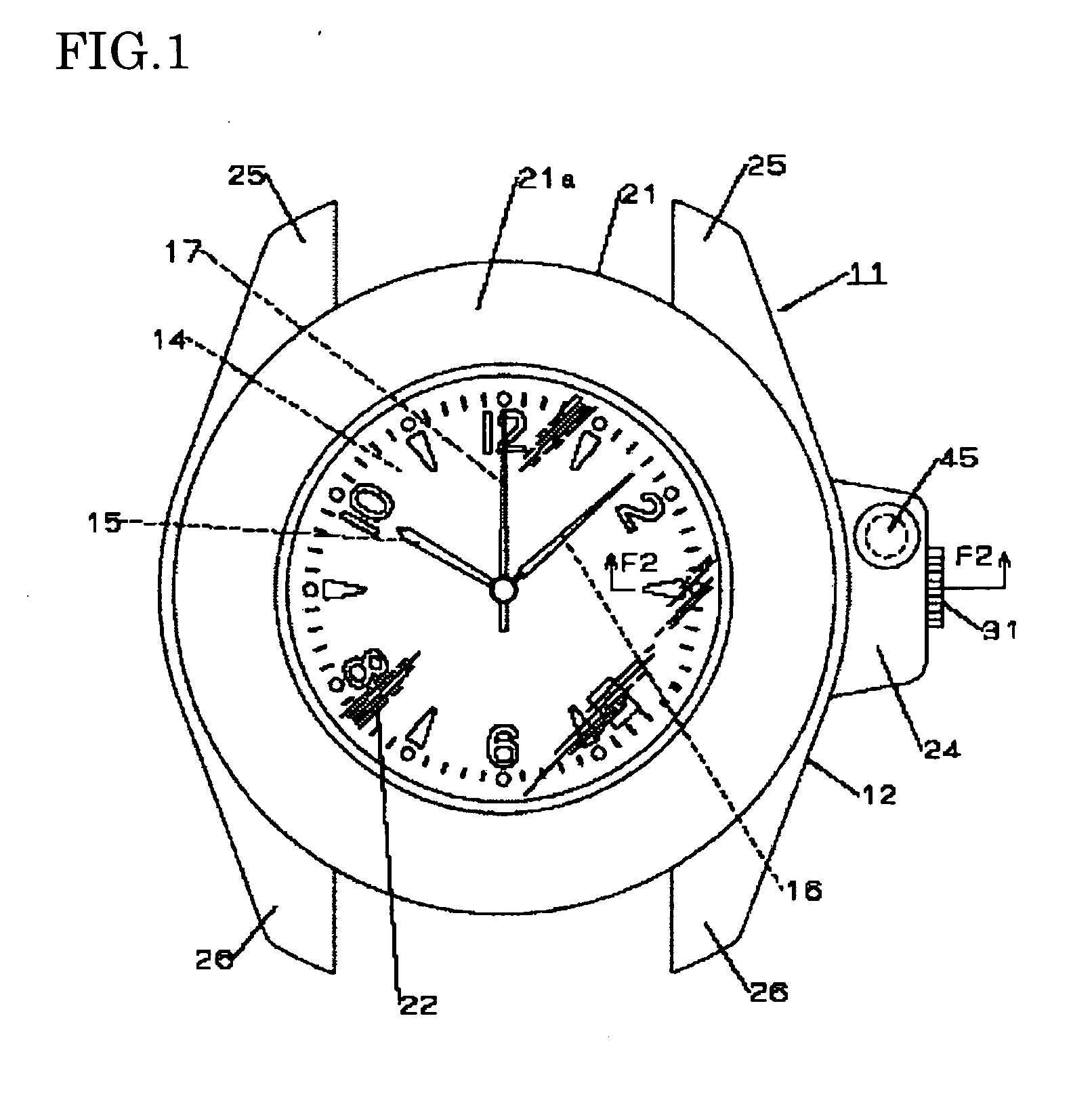
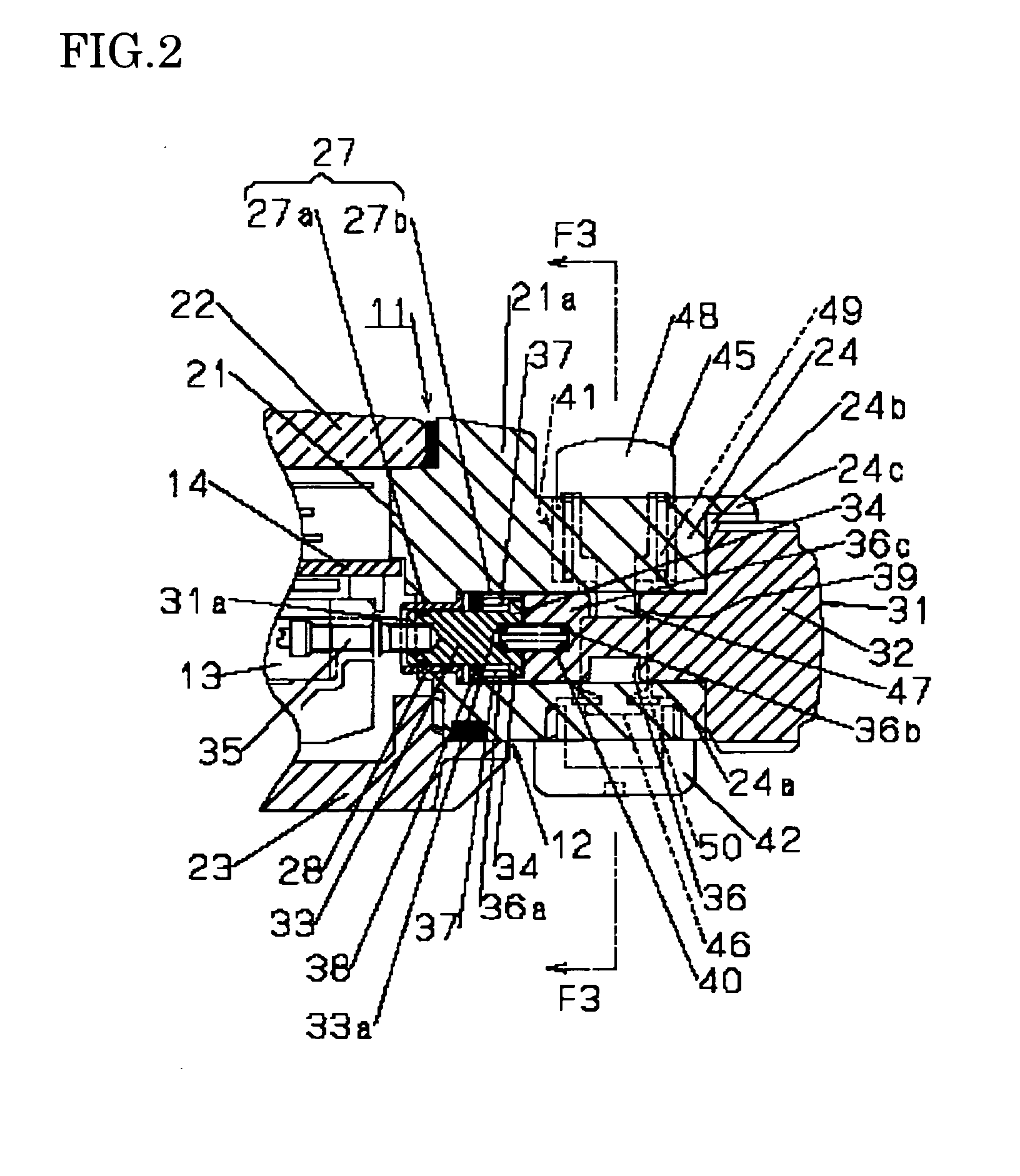
[0047]In the following, the present invention will be described in detail with reference to FIGS. 1 through 9.

[0048]In FIGS. 1, 2, 5, and 6, numeral 11 indicates a portable watch such as a wristwatch. As shown in FIGS. 2 and 6, inside a watch exterior member 12 of the wristwatch 11, there are provided a built-in component such as a watch movement 13 and a time display portion such a circular dial 14. The display on the dial 14 is effected by time indicating hands driven by the watch movement 13, more specifically, by a short hand 15, a long hand 16, and a minute hand 17 shown in FIGS. 1 and 5.

[0049]As shown in FIGS. 2 and 6, the watch exterior member 12 is equipped with a case band 21, a glass 22, and a case back 23. The case band 21 is formed in an annular shape of a metal such as stainless steel or titanium or synthetic resin. The glass 22 allowing the dial 14 to be viewed from the outside is attached liquid-tight to the front portion of the case band 21. The case back 23 is forme...

second embodiment

[0088]In the second embodiment, the member mounting portion 41 is formed as a bottomed round hole. The member mounting portion 41 crosses the crown mounting hole 27 in the thickness direction (vertical direction) of the case band, and the member mounting portion 41 and the crown mounting hole 27 communicate with each other at this crossing portion. The upper end of the member mounting portion 41 is open in the upper surface of the protrusion 24, and a plug 55 is attached to the protrusion 24 so as to close this opening portion.

[0089]The plug 55 has a rectangular guide hole 56. The guide hole 56 is formed to extend such that its longitudinal direction in plan view is orthogonal to the direction in which the protrusion 24 protrudes. Further, one end portion in the longitudinal direction of the guide hole 56 is provided directly above the crossing portion so as to be opposed to the crossing portion (communicating portion) from above.

[0090]In the second embodiment, the crown lock member...


PUM


Abstract

A portable watch is equipped with a watch exterior member, a crown, a crown lock button, and an urging member. In a case band with which the exterior member is equipped, there are formed a crown mounting hole and a member mounting portion communicating with this hole and vertically perpendicular thereto. The crown is arranged in the hole. The crown has a crown shaft portion passed through the hole and a crown head portion continuous therewith. The crown shaft is provided with a lock groove continuous in the peripheral direction. The lock button accommodated in the mounting portion has a button head portion (operation end portion) protruding from the mounting portion. The button is movable between a lock position where it is engaged with the groove to constrain the crown and a lock canceling position where it is detached from the groove to cancel the constraint of the crown, and is arranged at the lock canceling position through a one-touch operation of the button head portion. The watch is characterized in that the button is arranged at the lock position by an urging member accommodated in the mounting portion.

Description

BACKGROUND OF THE INVENTIONField of the Invention[0001]The present invention relates to a portable watch such as a wristwatch or a pocket watch equipped with a structure helping to prevent an erroneous operation of a crown while the watch is being carried about.[0002]In a wristwatch, it is required that the crown should be prevented from being erroneously operated while the watch is being carried about, that is, that the crown should be prevented from being erroneously pulled out and rotated inadvertently.[0003]For this purpose, there is known as a prior-art technique capable of locking the crown, a watch in which a male screw portion is provided in the outer periphery of a tubular protrusion protruding to the case band exterior side of a winding stem pipe fixed to the case band, in which the crown is formed by a shaft portion inserted into the winding stem pipe and a crown head portion capable of receiving the tubular protrusion and equipped with a female screw portion, and in whic...

Claims


Application Information

Patent Timeline
IPC IPC(8): G04B37/06
CPCG04B3/043
Inventor HOZUMI, YOSHIOITOH, KINSHURO
Owner SEIKO INSTR INC
Learn More