

Hinged Fiber Optic Module Housing and Module
a fiber optic module and fiber optic module technology, applied in the field of fiber optic module housing and module, can solve the problems of fiber optic module not passing the loss insertion test, operator may not fully establish a fiber optic connection to a particular fiber optic component, and fiber optic components may be difficult to access, etc., to achieve the effect of improving access
- Summary
- Abstract
- Description
- Claims
- Application Information
AI Technical Summary
Benefits of technology
Problems solved by technology
Method used
Image

Examples
Embodiment Construction
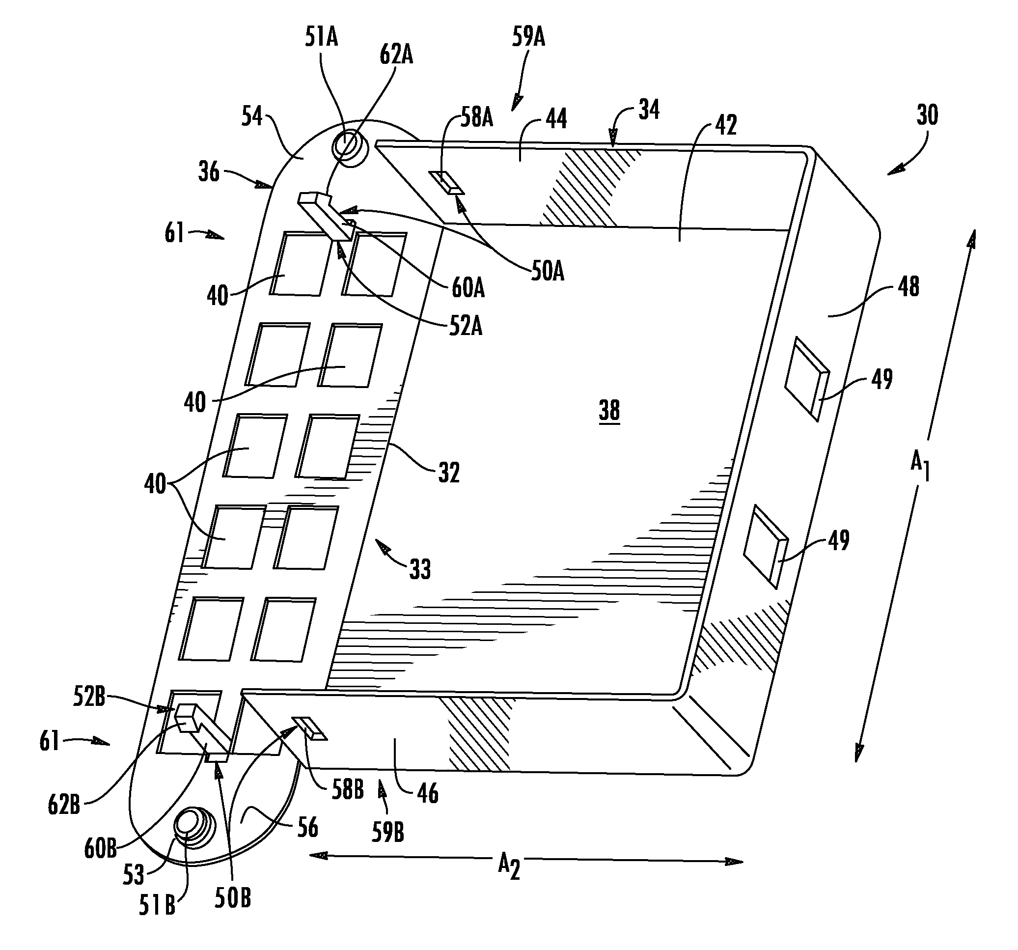
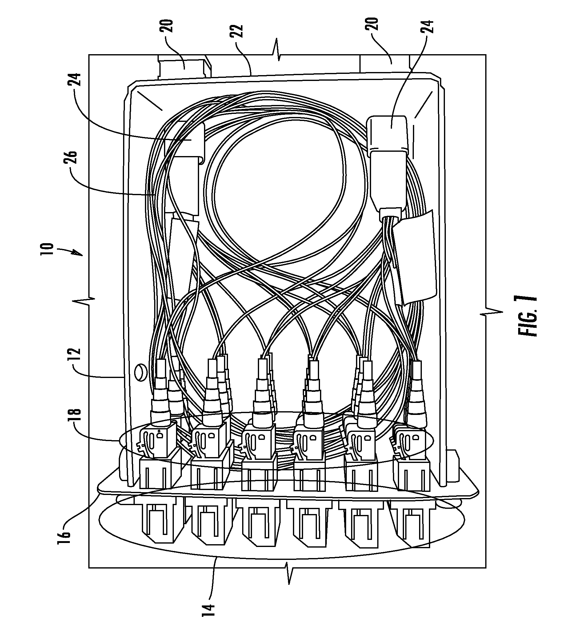
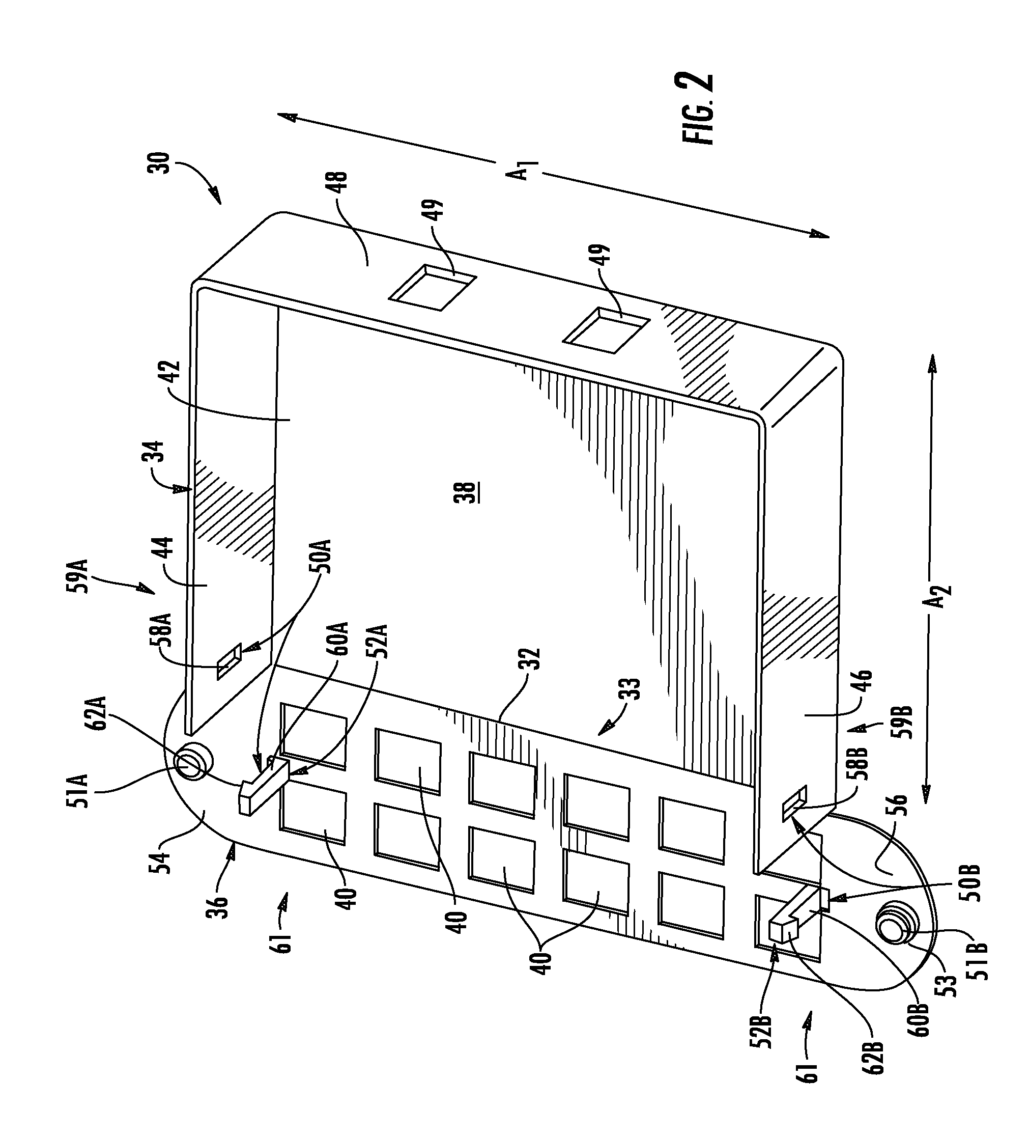
[0007]Embodiments disclosed in the detailed description include fiber optic module housings and modules. The fiber optic module housing comprises at least one hinge disposed between a portion of a main body and a panel configured to support one or more fiber optic components. The panel can be opened from and closed against or substantially against the main body about the hinge. In this manner, the panel can be opened from the main body to provide enhanced access to the panel, fiber optic components disposed in the panel, and / or the internal chamber of the fiber optic module housing. In certain embodiments, the hinge is a living hinge made from a material joining the panel and a portion of the main body that allows the panel to bend along the living hinge with respect to the main body. The panel and main body may be constructed out of one part with the living hinge disposed in the part therebetween to provide a hinge between the panel and main body. In other embodiments, the hinge is...
PUM
 Abstract
Description
Claims
Application Information