Image forming apparatus

a technology of image forming apparatus and rotating cam, which is applied in the direction of electrographic process apparatus, instruments, optics, etc., can solve the problems of linear uneven density of images, affecting and reducing the linear speed of image carriers. , to achieve the effect of increasing the life of rotating cams and preventing shock jitter and transfer failures

Active Publication Date: 2010-09-02
RICOH KK
View PDF3 Cites 62 Cited by
  • Summary
  • Abstract
  • Description
  • Claims
  • Application Information

AI Technical Summary

Benefits of technology

[0009]The present invention was contrived in view of the problems mentioned above, and it is an object of the present invention to provide an image forming apparatus that is capable of preventing the shock jitter and transfer failures and increasing the life of a rotating cam.

Problems solved by technology

Use of a thick sheet as a recording sheet in this type of image forming apparatus often causes a linear unevenness in the density of the image, which is called “shock jitter.” When the thick sheet enters a transfer nip, the burden on an image carrier drastically increases and the linear speed of the image carrier is significantly reduced instantly, causing this density unevenness.
However, the increase of the abovementioned inter-shaft distance might cause a transfer failure due to a lack of transfer pressure.
However, the problem of this configuration is that the convex parts of the rotating cams are worn out in a short period of time by frequently driving the rotating cam, significantly reducing the life of the rotating cams.

Method used


Image

  • Image forming apparatus
  • Image forming apparatus
  • Image forming apparatus

Examples


Embodiment Construction

)

[0029]Hereinafter, an embodiment in which the present invention is applied to a tandem color copy machine (to be simply referred to as “copy machine” hereinbelow) is described.

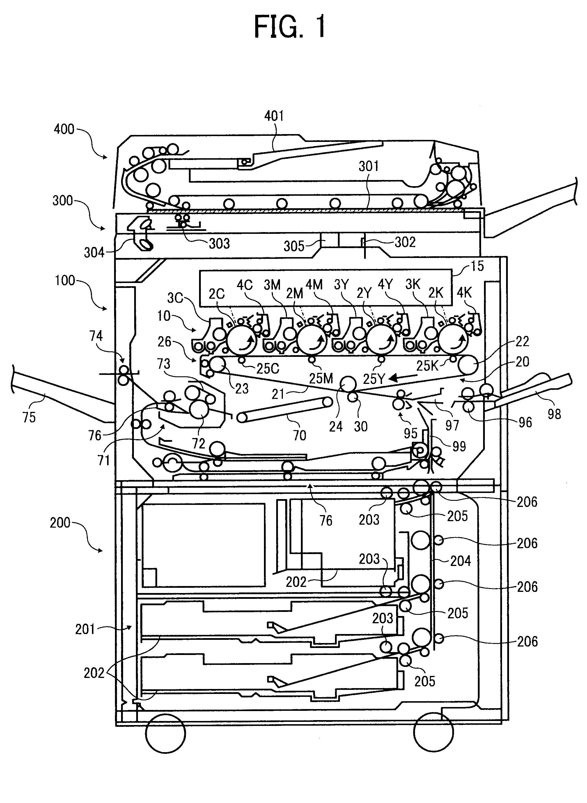
[0030]FIG. 1 shows a schematic configuration of the copy machine according to the present embodiment. This copy machine has a printer 100, sheet feeding part 200, scanner 300 attached to the top of the printer part 100, and automatic document feeder (ADF) 400 attached to the scanner 300.

[0031]The printer 100 has an endless belt-type intermediate transfer belt 21 as an image carrier. The intermediate transfer belt 21 is wrapped around a driving roller 22, driven roller 23 and secondary transfer counter roller 24 so as to form an inverted triangle as viewed from the side, and is moved endlessly in the clockwise direction by being driven by driving roller 22. Four image forming units 1C, M, Y and K for forming C (cyan), M (magenta), Y (yellow) and K (black) toner images are arranged above the intermediate transf...


PUM


Abstract

To provide an image forming apparatus capable of increasing the life of a rotating cam while preventing the occurrence of a shock jitter and transfer failure. The image forming apparatus is configured to execute a forced movement process for rotating the rotating cam to forcibly move a secondary transfer roller against a biasing force of a bias coil spring at a pre-entry timing prior to the entry of the front edge of a recording sheet into a secondary transfer position, and a pressure intensifying process for rotating the rotating cam to increase transfer pressure at a timing immediately after the entry of the front edge of the recording sheet into the secondary transfer position. As the forced movement process, the image forming apparatus executes, alternately, a first forced movement process for normally driving and rotating the rotating cam, and a second forced movement process for inversely driving and rotating the rotating cam, at a predetermined timing.

Description

BACKGROUND OF THE INVENTION[0001]1. Field of the Invention[0002]The present invention relates to an image forming apparatus that has a function of forcibly moving an abutting body away from an image carrier by driving a rotating cam, the abutting body being capable of abutting the image carrier by means of a biasing force of a biasing part to form a transfer nip.[0003]2. Description of the Related Art[0004]Use of a thick sheet as a recording sheet in this type of image forming apparatus often causes a linear unevenness in the density of the image, which is called “shock jitter.” When the thick sheet enters a transfer nip, the burden on an image carrier drastically increases and the linear speed of the image carrier is significantly reduced instantly, causing this density unevenness.[0005]The image forming apparatus described in Japanese Patent Application Laid-open No. H10-83124 inhibits the occurrence of the shock jitter as follows. In this image forming apparatus, a transfer rolle...

Claims


Application Information

Patent Timeline
Patent Type & Authority Applications(United States)
IPC IPC(8): G03G15/16
CPCG03G15/161G03G15/0131
Inventor MINBU, RYUICHISENGOKU, KENJIFUJITA, JUNPEIICHIHASHI, OSAMU
Owner RICOH KK
Why Eureka
Try Eureka