Combination bathtub and spa

a bathtub and spa technology, applied in the field of bathtubs, can solve the problems of all the water remaining in the system, and achieve the effect of facilitating the understanding of the invention

Active Publication Date: 2010-09-09
MAY MFG
View PDF51 Cites 22 Cited by
  • Summary
  • Abstract
  • Description
  • Claims
  • Application Information

AI Technical Summary

Problems solved by technology

If the tub is full of water when the purging system is operated, actuation of the air pump will cause pressurized air to aerate the water flowing through the jet nozzles; however, if the tub is empty, actuation of the air pump will cause air to flow through the jetted circulation system, thereby forcing substantially all of the water remaining in the system out through the jet nozzles.

Method used


Image

  • Combination bathtub and spa
  • Combination bathtub and spa
  • Combination bathtub and spa

Examples


second embodiment

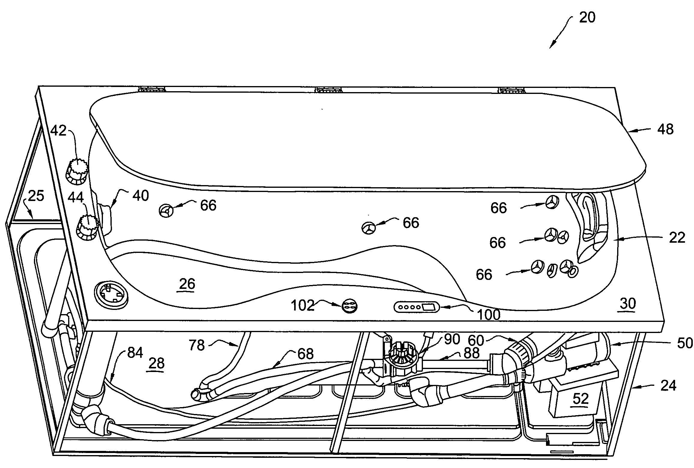
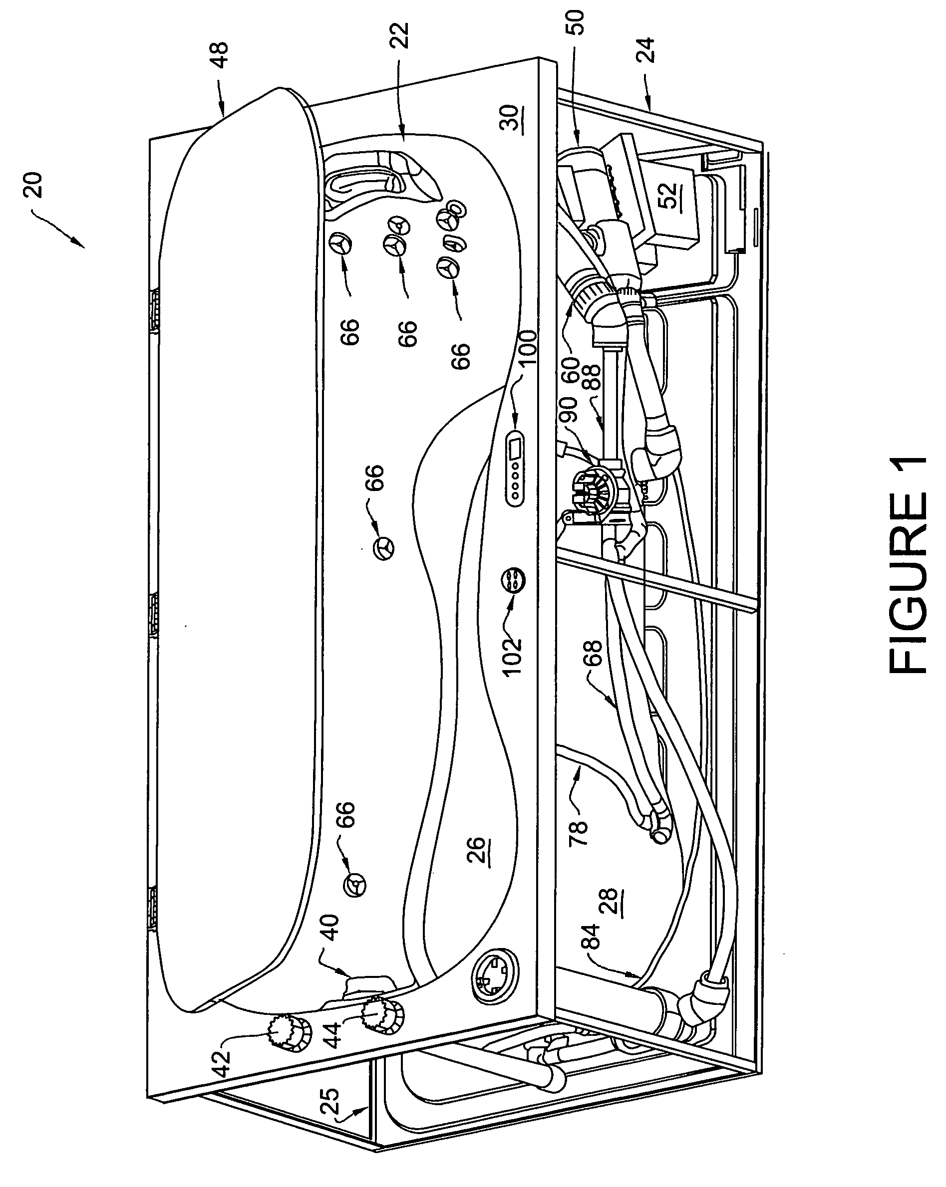
[0048]FIG. 7 illustrates the invention that is similar to that shown in FIGS. 1-6, in that it comprises a combination bathtub and spa utilizing a single pump. As shown in FIG. 7, combination bathtub and spa 120 comprises tub enclosure 122 that is adapted to contain a quantity of water and is supported by base 125. Like tub enclosure 22, tub enclosure 122 comprises tub floor 126 and upstanding sidewall 128 which is integrally attached to and surrounds the floor. Combination 120 also includes supporting rim 130, which is disposed around and integrally attached to the sidewall. Combination 120 also includes drain 132 that is mounted in the floor of the tub enclosure and a conventional drain valve (not shown) that may be opened to drain water from the tub enclosure, or closed to retain water therein. Water is supplied to the tub enclosure by means of cold and hot water supply lines (not shown), and the flow of water is directed through faucet 140 by cold water valve 142 and hot water va...

embodiment 20

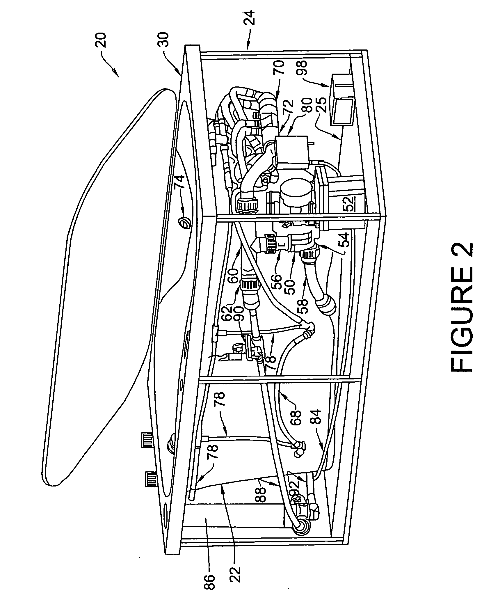
[0050]Combination 120 also includes filter 186 and second port 187, which is located in the sidewall of the tub enclosure. Second suction line 188 extends from second port 187 to filter inlet 189 to provide a path for water from the tub enclosure to filter 186. Filtered water passes out of filter 186 through filter outlet 190 to inlet line 155. A control valve, such as solenoid valve 192 (similar to valve 90 of embodiment 20) or another user-controlled valve, is mounted within inlet line 155 and is adapted to be opened to allow the flow of filtered water through line 155 or closed to stop such flow.

[0051]Heater 160 is mounted in inlet line 155 and is adapted to be activated to heat the water therein. Combination 120 also includes a plurality of jet nozzles 166 mounted in the sidewall of the tub enclosure. Each jet nozzle is connected by one or more jet nozzle supply lines 168 to water manifold 170, which is connected to outlet 156 of pump 150. Air control valve 174 is mounted in sup...

embodiment 120

[0057]If a user sets the control switch of embodiment 120 to the bathtub mode, controller 198 will close control valve 192 to prevent the flow of water through the filter. With valve 192 remaining closed (and the water level at or above the predetermined level at which controller will permit pump 150 to operate), activating pump 150 at either the low-flow rate or the high-flow rate will cause water to flow from the tub enclosure through first port 159 and first suction line 158 into pump inlet line 155, past heater 160, into pump inlet 154, out pump outlet 156 and into water manifold 170. The water may be heated as it passes through heater 160, as controlled by the user from control panel 200. From manifold 170, water will be passed through various jet nozzle supply lines 168 and into the tub enclosure through jet nozzles 166. A user may also open air control valve 174, manually or by means of control panel 200, causing air to be drawn through air manifold 176 and air lines 178 to b...


PUM


Abstract

A combination bathtub and spa includes a tub enclosure that is adapted to contain a quantity of water, a drain having a drain valve that may be opened to drain water from the tub enclosure or closed to retain water therein, a supply system for supplying water to the tub enclosure, and a lid that is adapted to removably cover the tub enclosure. The combination bathtub and spa also includes a pump having an inlet and an outlet, a suction line that provides a path for water from the tub enclosure to the inlet of the pump, a jet nozzle that is located in the sidewall of the tub enclosure, and a jet nozzle supply line that provides a path for water from the outlet of the pump to the jet nozzle. A filter is provided to filter the water that flows into the tub enclosure, as well as a heater for heating the water that flows into the tub enclosure. A control valve is adapted to open to allow water to flow through the filter or to close to stop the flow of water through the filter.

Description

FIELD OF THE INVENTION[0001]The present invention relates generally to spas, and more particularly to a tub assembly that can be used as either a jetted bathtub or a recirculating spa.BACKGROUND OF THE INVENTION[0002]Bathtubs have been known and used for centuries. Modern bathtubs may comprise a molded shell which forms a tub enclosure having a floor and an upstanding sidewall. The shell is typically constructed of fiberglass, plastic or a similar material, or a composite of such materials. Modern bathtubs are also provided with hot and cold water valves and supply lines which are attached to a supply nozzle or nozzles. In addition, a modern bathtub will include a drain having a drain valve that may be opened to remove water from the tub enclosure. A jetted bathtub is similar to a standard bathtub, but typically includes a pump and associated plumbing which is adapted to discharge water, usually mixed with air, into the enclosure through a plurality of jet nozzles that are mounted i...

Claims


Application Information

Patent Timeline
Patent Type & Authority Applications(United States)
IPC IPC(8): A47K3/10
CPCA61H33/005A61H33/02A61H2033/0037A61H33/6068A61H2201/0207A61H33/6063A61H2033/0058
Inventor MAY, THOMASCHANDRA, LODYHENDRICKS, GEORGE
Owner MAY MFG
Why Eureka
Try Eureka