
Metal laminate gasket

a metal laminate and gasket technology, applied in the direction of engine sealing, machine/engine sealing, etc., can solve the problems of increasing costs, achieve the effect of improving the sealing property, increasing the surface pressure of the bead portion in the metal laminate gasket, and improving the sealing property of the bead portion

Active Publication Date: 2010-09-09
ISHIKAWA GASKET CO LTD
View PDF11 Cites 6 Cited by
  • Summary
  • Abstract
  • Description
  • Claims
  • Application Information

AI Technical Summary

Benefits of technology

"The present invention provides a metal laminate gasket with improved sealing properties. The gasket includes a plurality of metal plates, with concavities and convexities on one metal plate that increase the apparent plate thickness. These concavities and convexities have a smaller size and lower deformation compared to the bead, and are positioned on a flat portion where the plate thickness increases. This results in increased surface pressure on the bead, improving its sealing ability without the need for additional metal plates."

Problems solved by technology

However, if the metal plate such as the shim and the like is used, not only the metal plate with a required thickness has to be prepared but also the metal plate thereof has to be laminated in a required position at the time of assembly, so that the cost goes up.

Method used


Image

  • Metal laminate gasket
  • Metal laminate gasket

Examples


first embodiment

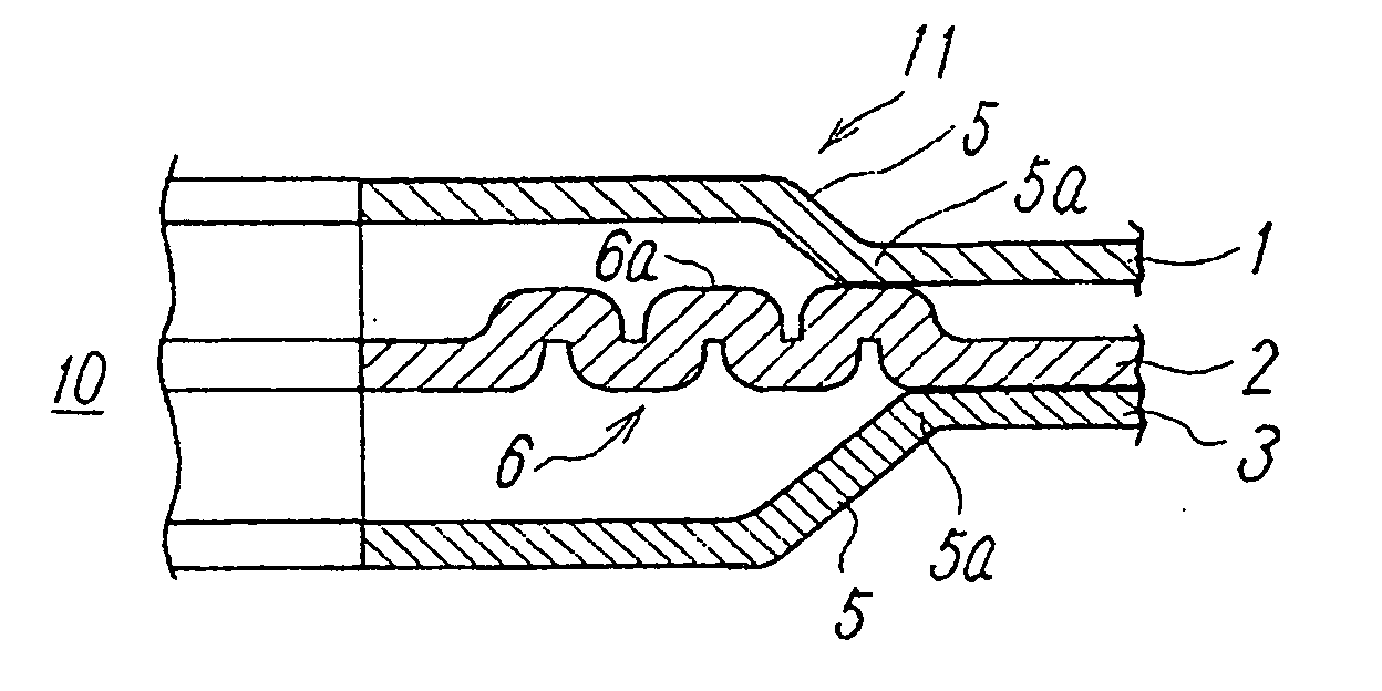
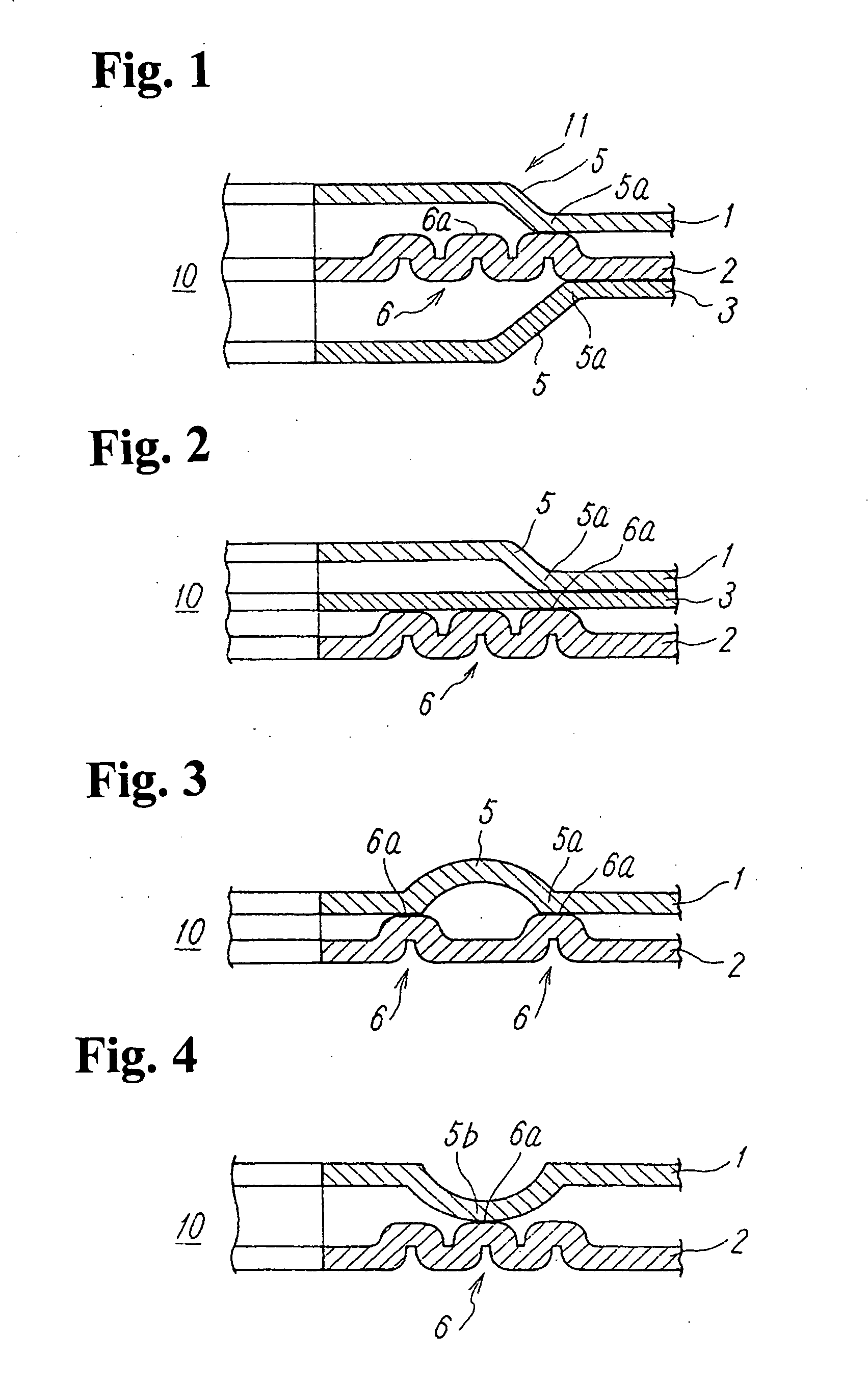
[0017]In addition, specifically, the metal laminate gasket of the first embodiment shown in FIG. 1 includes the first to third metal plates 1 to 3, and a bead (half bead) 5 is provided respectively in the position to be sealed in the first metal plate 1 and the third metal plate 3. In the metal plate 2 to which the first metal plate 1 and the third metal plate 3 are laminated, the concavities and convexities 6 for increasing the apparent plate thickness are provided in the position corresponding to the foot portions 5a of the bead 5 of the first and third metal plates 1, 3.

[0018]The concavities and convexities 6 differ from the bead which is presumed to be elastically deformed, and are formed by, for example, a coining process and the like. Heights and widths of the concavities and convexities 6 are enough smaller than those of the bead 5, and the deformation due to a surface pressure is made very smaller than that of the bead 5. As shown in the figures, a plurality of concave porti...

second embodiment

[0021]In the second embodiment, the foot portion 5a of the bead 5 is disposed on the flat portions 6a wherein the plate thickness increases due to the concavities and convexities 6 via the third metal plate 3. However, compared to the case wherein the foot portion 5a of the bead 5 is disposed directly on the concavities and convexities 6, there is no particular difference for an improvement effect of the sealing property of the bead portion.

third embodiment

[0022]The metal laminate gasket of the third embodiment shown in FIG. 3 comprises the first metal plate 1 to which the bead (full bead) 5 is provided in the position to be sealed, and the second metal plate 2 which is laminated on an opposite face side of a projected face side of the bead 5. The concavities and convexities 6 for increasing the apparent plate thickness are provided in the position corresponding to both foot portions 5a of the bead 5 of the first metal plate 1 in the second metal plate 2, and both foot portions 5a of the bead 5 are disposed on the flat portions 6a wherein the plate thickness due to the concavities and convexities c.

[0023]The other structures and operations are the same as those in the case of the first embodiment.


PUM

PropertyMeasurementUnit
thicknessaaaaaaaaaa
heightaaaaaaaaaa
widthaaaaaaaaaa

Abstract

A metal laminate gasket includes a plurality of metal plates including a first metal plate having a first hole to be sealed and a bead around the first hole, and a second metal plate laminated under the first metal plate and having a second hole corresponding to the first hole. Concavities and convexities are formed at the second metal plate concentrically around the second hole for increasing an apparent plate thickness of the second metal plate. The concavities and convexities are provided continuously at a position corresponding to the foot portion or the top portion of the bead of the first metal plate. The concavities and convexities have a height and width smaller than those of the bead, and have a deformation characteristic due to a surface pressure when compressed, smaller than that of the bead.

Description

BACKGROUND OF THE INVENTION AND RELATED ART STATEMENT[0001]The present invention relates to a metal laminate gasket constituted by laminating a plurality of metal plates, wherein a surface pressure of a bead provided in a position to be sealed in an arbitrary metal plate among the plurality of metal plates, is increased.[0002]Conventionally, the metal laminate gasket to which the bead is provided in the position where the laminated metal plates should be sealed, is quite-generally well known. The bead is effective for increasing a surface pressure on the bead thereof and performing a full sealing property; however, in order to increase the surface pressure thereof more and improve the sealing property, there is a limit even if the height or width of the bead, the curvature of a curved portion, and the like are revised. As a result, the plate thickness of the bead portion is required to increase by a shim and the like. However, if the metal plate such as the shim and the like is used...

Claims


Application Information

Patent Timeline
Patent Type & Authority Applications(United States)
IPC IPC(8): F02F11/00F16J15/08
CPCF16J15/0825
Inventor IMAI, TOSHIHIRO
Owner ISHIKAWA GASKET CO LTD
Learn More