
Image displaying apparatus

Inactive Publication Date: 2010-09-09
SANYO ELECTRIC CO LTD
View PDF9 Cites 6 Cited by
  • Summary
  • Abstract
  • Description
  • Claims
  • Application Information

AI Technical Summary

Problems solved by technology

However, in the related art, the RGB data of the vertical stripe array is laid out in the vertical two lines, resulting in degradation in image quality.

Method used


Image

  • Image displaying apparatus
  • Image displaying apparatus
  • Image displaying apparatus

Examples


Embodiment Construction

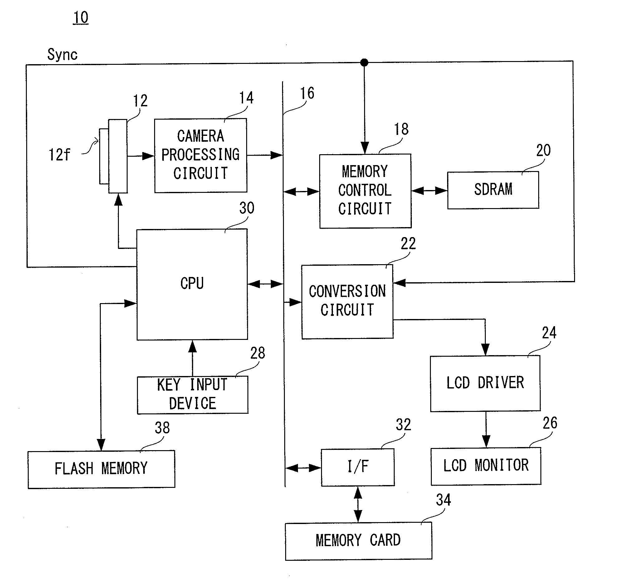
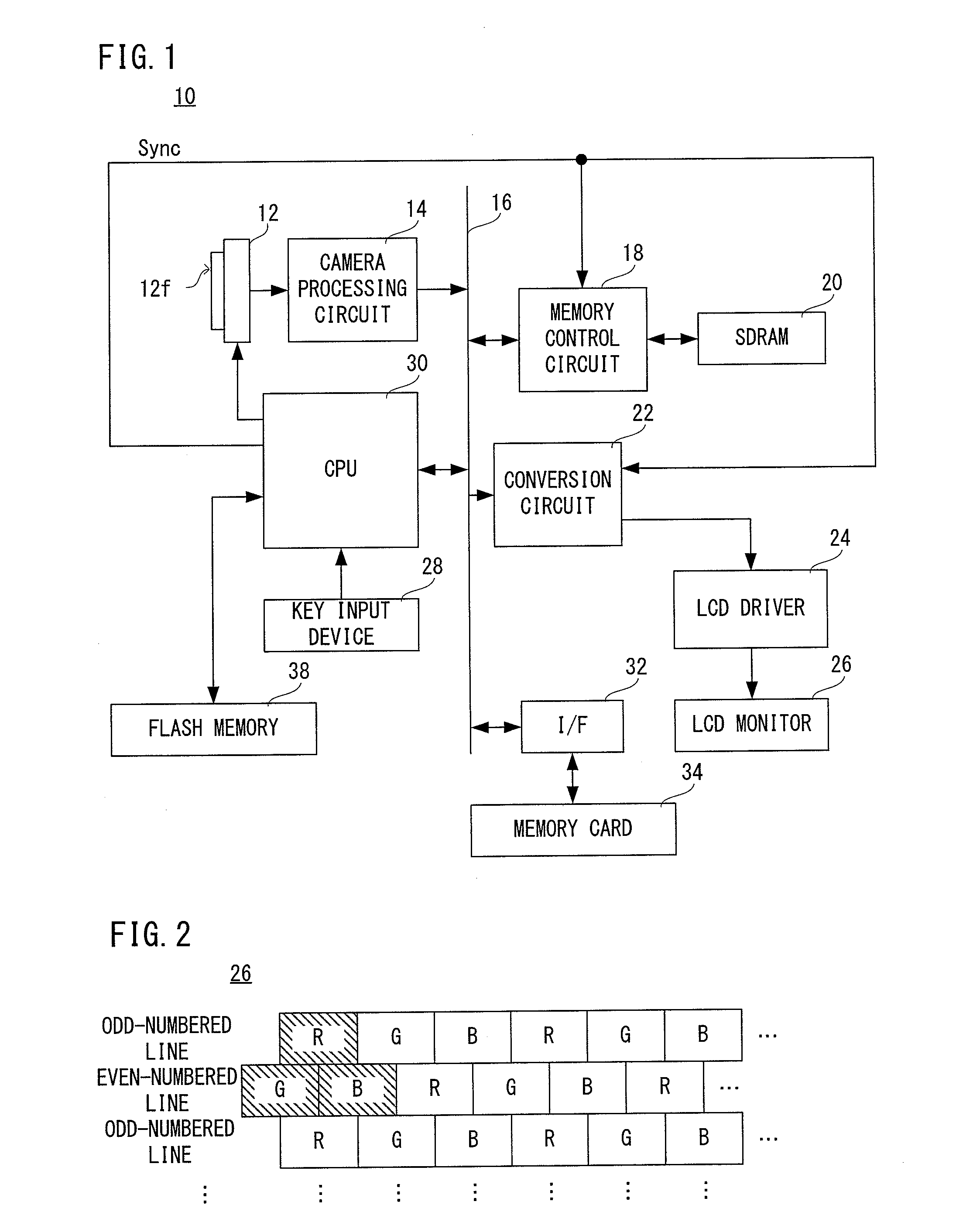
[0021]Referring to FIG. 1, a digital camera 10 of this embodiment includes an image sensor 12. An optical image of an object scene is irradiated onto the image sensor 12. On an imaging area 12f of the image sensor 12, a photoreceptor corresponding to 1600×1200 pixels, for example, is set, and on the imaging area 12f, electric charges corresponding to the optical image of the object scene, that is, a raw image signal of 1600×1200 pixels is generated by a photoelectronic conversion.

[0022]When a power source of the digital camera 10 is turned on, a CPU 30 instructs the image sensor 12 to repeat a pre-exposure and a thinning-out reading in order to display a real-time motion image, that is, a through image of the object on an LCD monitor 26 being a display apparatus. The image sensor 12 repetitively executes the pre-exposure and the thinning-out reading of the raw image signal thus generated in response to a synchronization signal (Vsync) which is generated for each 1 / 30 seconds. A raw ...


PUM


Abstract

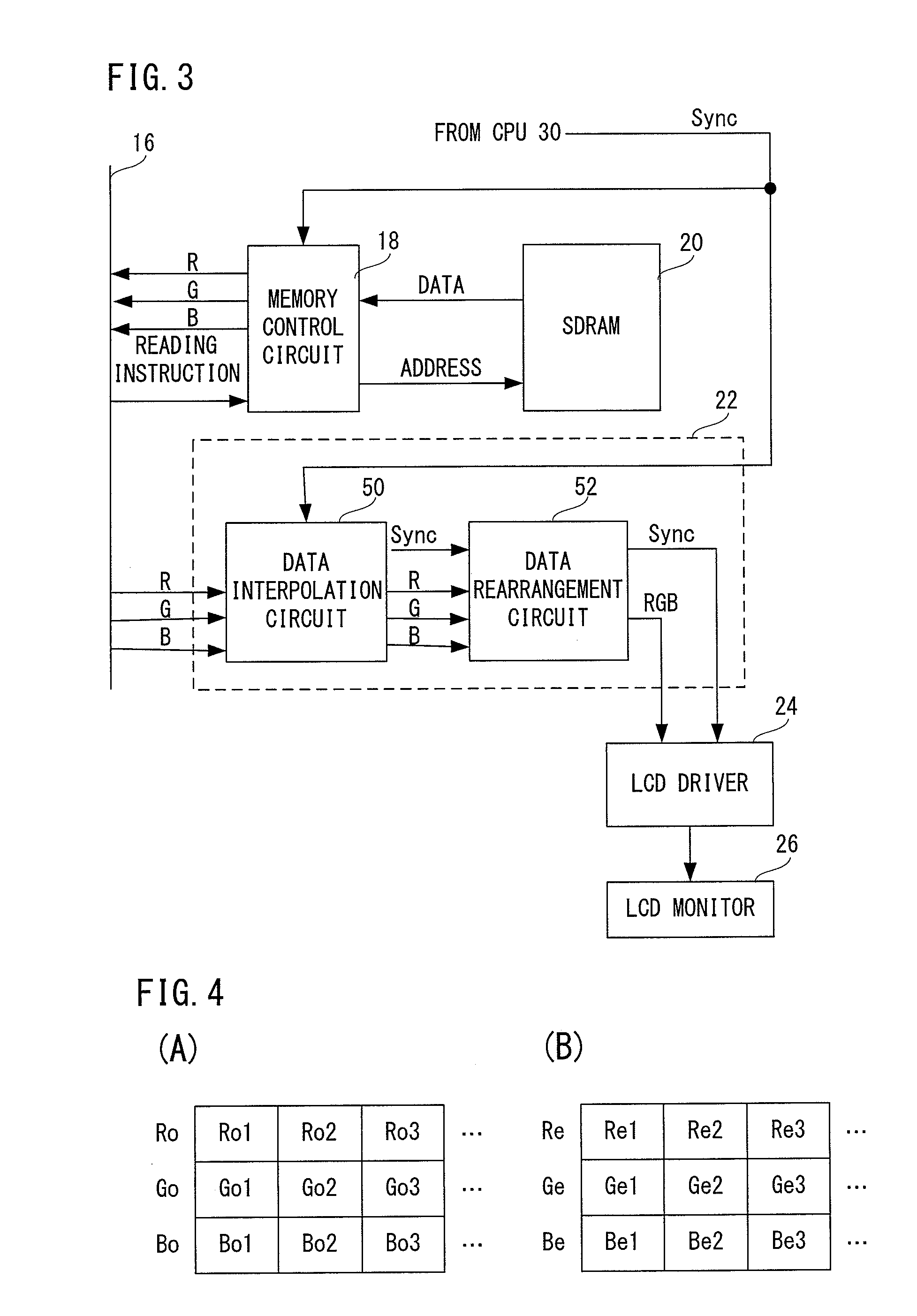
An image displaying apparatus includes a display with delta array. If an image is displayed on the basis of image data in an RGB format arrayed in a stripe pattern, data of color values R, G and B are input to a calculator. The calculator performs a weighted average on color values of adjacent pixels in a lateral direction to calculate each color value, and a rearranger rearranges calculated respective color values so as to conform to the delta array. Then, a driver displays an image on the basis of the color values which are rearranged so as to conform to the delta array.

Description

CROSS REFERENCE OF RELATED APPLICATION[0001]The disclosure of Japanese Patent Application No. 2009-054114 is incorporated herein by reference.BACKGROUND OF THE INVENTION[0002]1. Field of the Invention[0003]The present invention relates to an image displaying apparatus. More specifically, the present invention relates to an image displaying apparatus displaying an image on an LCD monitor.[0004]2. Description of the Related Art[0005]Conventionally, an image displaying apparatus displaying an image on an LCD monitor is known.[0006]As one example of the related art, when RGB data of a vertical stripe array is displayed on a display panel with a delta pixel array, a screen display is performed by developing the RGB data in vertical two lines (V direction) and laying out them. Thus, this driving apparatus can perform the screen display by an original aspect ratio.[0007]However, in the related art, the RGB data of the vertical stripe array is laid out in the vertical two lines, resulting i...

Claims


Application Information

Patent Timeline
IPC IPC(8): G09G5/10
CPCG09G3/2003G09G3/3607G09G5/391H04N2101/00G09G2300/0452H04N7/0102G09G5/395
Inventor KIDO, KENICHI
Owner SANYO ELECTRIC CO LTD
Learn More