
Monitor camera

a technology for monitors and cameras, applied in the field of monitor cameras, can solve the problems of difficult to see the inside of the outer cover (b>4/b>) from the outside, and achieve the effect of preventing improper tampering and carrying out easily and efficiently

Active Publication Date: 2010-09-09
SANYO ELECTRIC CO LTD
View PDF10 Cites 20 Cited by
  • Summary
  • Abstract
  • Description
  • Claims
  • Application Information

AI Technical Summary

Benefits of technology

[0008]The present invention is to easily and efficiently perform the positioning of the open window (50) by adjusting the open window (50) in the direction of shooting by manually operating the outer cover (4) while the inner cover (5) and the outer cover (4) are attached to the pedestal (1).Means for Solving the Problems
[0012]With respect to the monitor camera (9) of the present invention, by manually performing the engagement of the outer cover (4) with the inner cover (5) and then rotating the outer cover (4), the inner cover (5) can be rotated together. Thus, after attaching the inner cover (5) and the outer cover (4) to the pedestal (1), the open window (50) of the inner cover (5) can be aligned in the direction of shooting. When attaching the inner cover (5) to the pedestal (1), no care needs to be taken about the position of the open window (50) of the inner cover (5). For this reason, the installation operation of the monitor camera (9) can be carried out easily and efficiently.
[0013]Moreover, because of the one-way clutch mechanism provided for the inner cover (5) and the outer cover (4), unless the outer cover (4) is rotated in a specific direction, the inner cover (5) cannot be rotated together. This, therefore, prevents improper tampering or the situation in which the orientation of the open window (50) is altered and the monitor camera (9) cannot take images properly.

Problems solved by technology

Therefore, the inside of the outer cover (4) is difficult to see from outside.

Method used


Image

  • Monitor camera
  • Monitor camera
  • Monitor camera

Examples


Embodiment Construction

[0022]Hereinafter, an embodiment of the present invention is described with reference to the drawings.

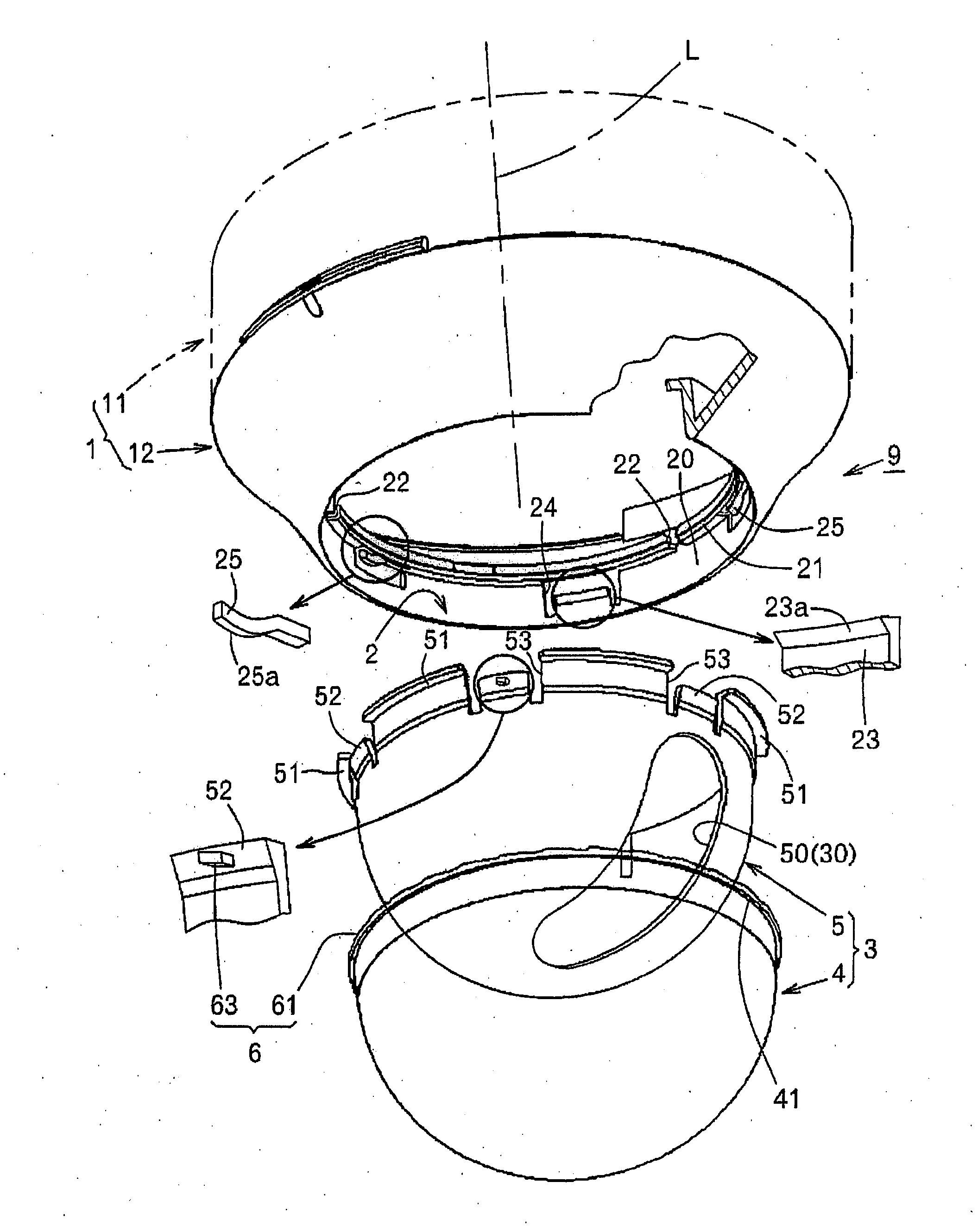
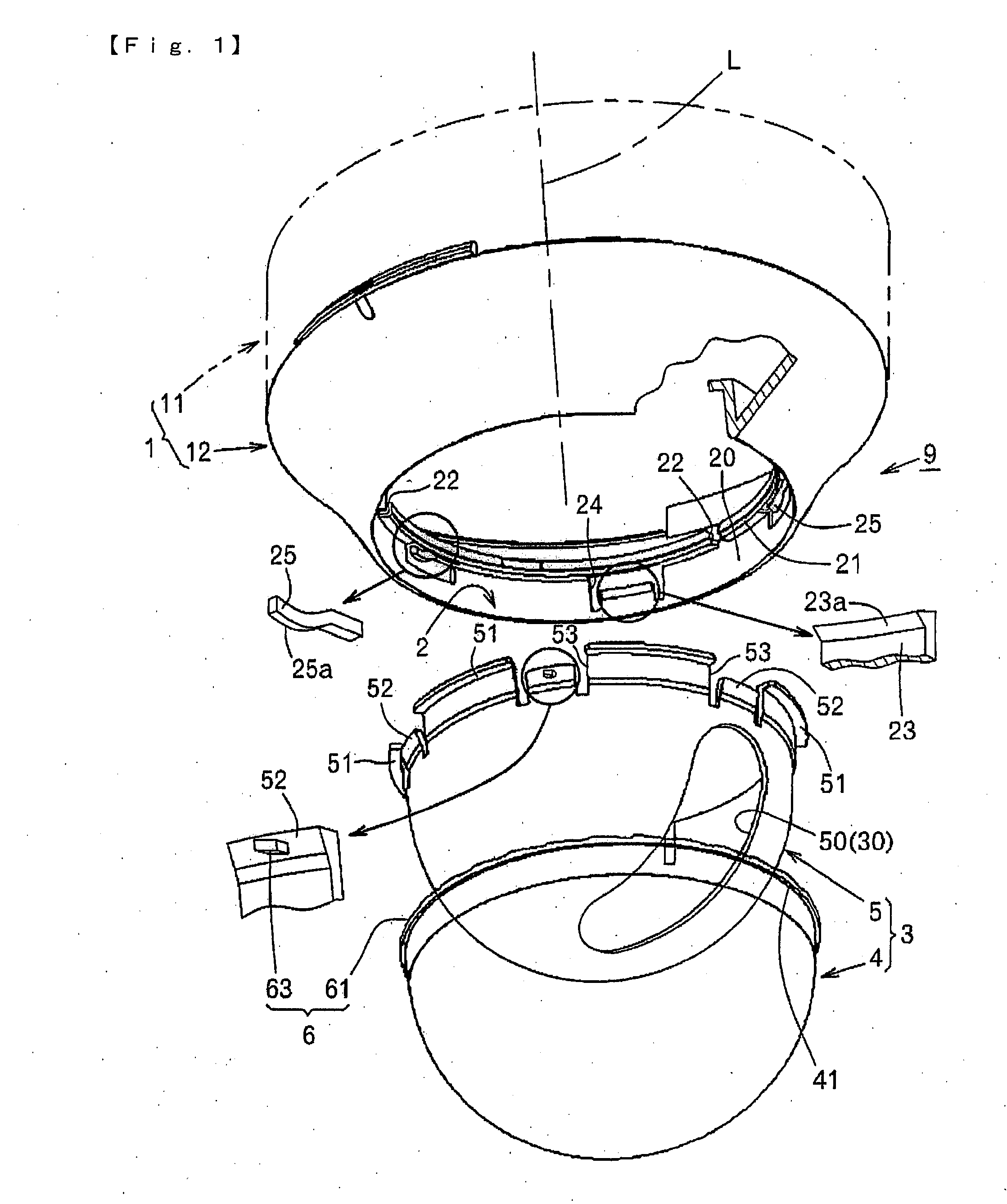
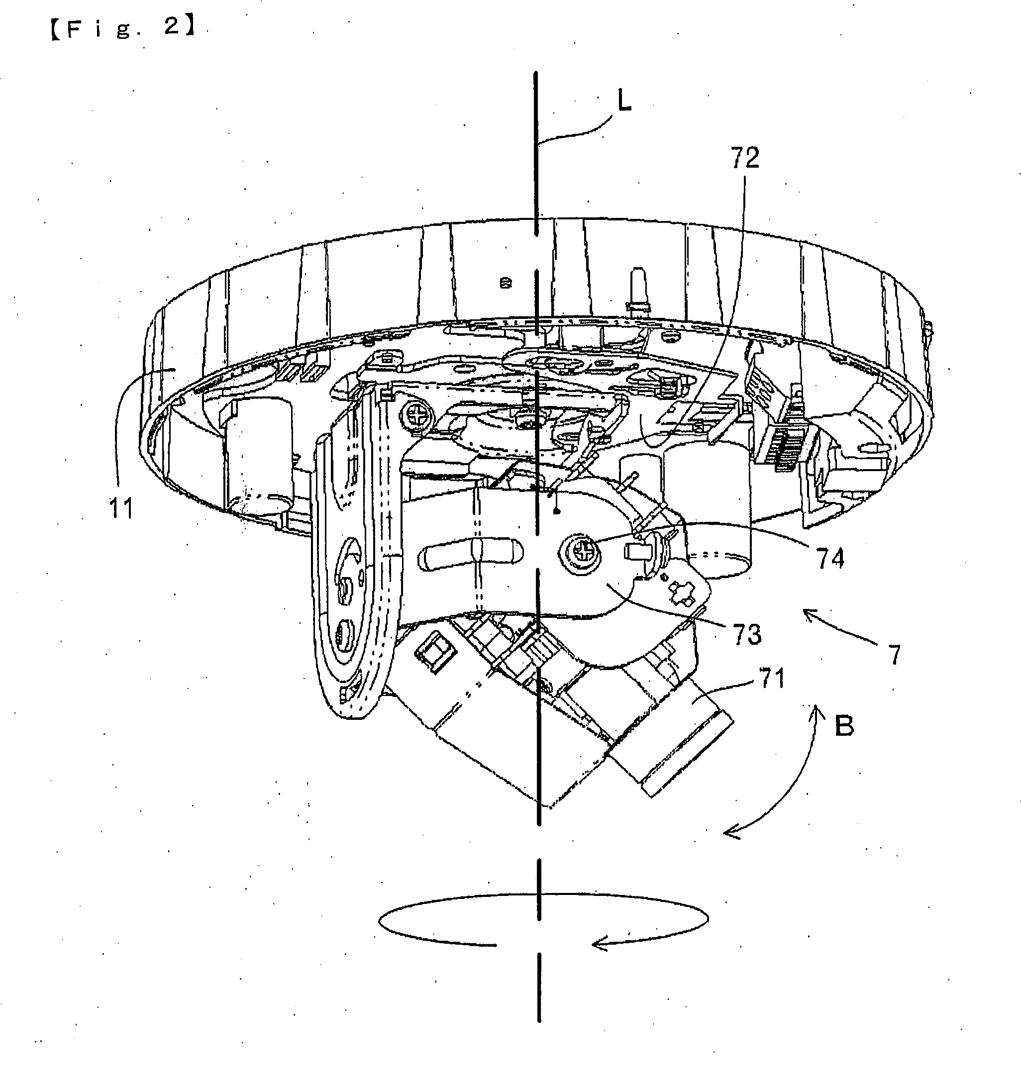
[0023]FIG. 1 is an exploded perspective view of a monitor camera (9) according to this embodiment. The monitor camera (9) is composed of a pedestal (1), an imaging device (7) (see FIG. 2) mounted on the pedestal (1), and a dome-type cover (3) covering the imaging device (7). The dome-type cover (3) is of a dual structure having an inner cover (5) and an outer cover (4).

[0024]FIG. 1 to FIG. 6 show the monitor camera (9) when it is attached to the ceiling facing downward. Hereinafter, “up” refers to the ceiling side and “down” refers to the ground side.

[0025]The pedestal (1) is composed of a pedestal body (11) and a pedestal cover (12) detachably fitted to the pedestal body (11). The dome-type cover (3) is attached to the pedestal cover (12), and as shown in FIG. 2, the imaging device (7) is attached to the pedestal body (11).

[0026]In this embodiment, as shown in FIG. 4(a), in a norma...


PUM


Abstract

The monitor camera (9) comprises a pedestal (1) to be attached to a mounting surface, an imaging device (7) rotatably attached so as to be rotatable around the central axis L of the pedestal (1), and a dome-type cover (3) having a window (30) and being rotatably attached to the pedestal (1) so as to cover the imaging device (7). The dome-type cover (3) includes an inner cover (5) having an open window (50) in the position corresponding to the window (30) and an outer cover (4) placed over the inner cover (5). The outer cover (4) and the inner cover (5) have an engagement part (6) at which both the covers (4) and (5) are engaged by a specific manual operation of the outer cover (4).

Description

TECHNICAL FIELD[0001]The present invention relates to a monitor camera having a dome-type cover of a dual-structure having an inner cover and an outer cover.BACKGROUND ART[0002]An example of a monitor camera (9) having a dome-type cover of a dual structure having an inner cover and an outer cover is shown in FIGS. 7 and 8. It includes a pedestal (1) to be attached to a mounting surface (95) such as a ceiling; an outer cover (4) through which it is hard to see inside from outside although the outer cover is made of a transparent material; an inner cover (5) having an open window (50); and an imaging device (7) that is disposed inside the inner cover (5) and can take images through the open window (50). To secure safety and enhance customer satisfaction and for other purposes in hospitals, hotels, department stores, etc., it is necessary that such a monitor camera is embedded in the ceiling, wall or the like of such buildings so as not to be noticeable. Therefore, the inside of the ou...

Claims


Application Information

Patent Timeline
IPC IPC(8): H04N5/225
CPCF16M11/12F16M11/126F16M11/18F16M13/02H04N5/2252G03B17/56G08B13/19619G08B13/1963G03B17/08G03B17/561H04N23/51
Inventor YAMAMOTO, KOJI
Owner SANYO ELECTRIC CO LTD
Learn More