Position detecting sensor

a position detecting and sensor technology, applied in the field of position detecting sensors, can solve the problems of difficult to achieve the improvement of operational efficiency and imposed constraints, and achieve the effect of enhancing the detection accuracy of the position detecting sensor, easy and efficient attachment, and stable and reliable fixing

Active Publication Date: 2017-06-01
SMC CORP
View PDF7 Cites 0 Cited by
  • Summary
  • Abstract
  • Description
  • Claims
  • Application Information

AI Technical Summary

Benefits of technology

[0025]In accordance with the above configuration, since the sensor main body can be positioned inside the sensor attachment groove, the distance between the displaceable body and the sensor main body can be a relatively close distance. Accordingly, the detection accuracy of the position detecting sensor can be enhanced. Further, since the sensor arrangement section is positioned between the two mounting members, the sensor arrangement section (sensor main body) can be fixed more stably and reliably with respect to the actuato...

Problems solved by technology

Therefore, an improvement in operational efficiency is not easily achieved, while additionally,...

Method used


Image

  • Position detecting sensor
  • Position detecting sensor
  • Position detecting sensor

Examples


Embodiment Construction

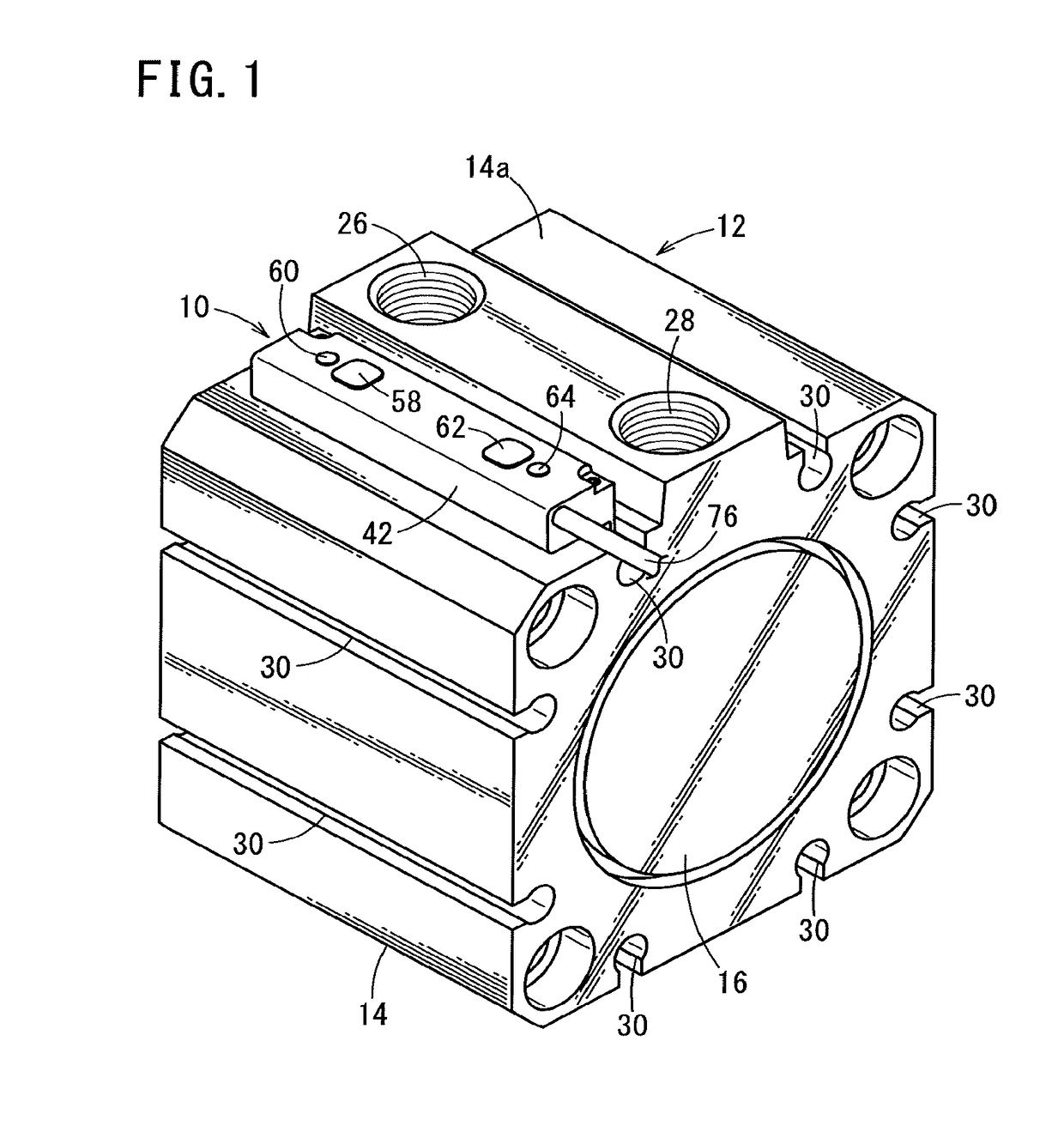
[0037]Below, a preferred embodiment concerning a position detecting sensor according to the present invention in relation to a cylinder device on which the positioning detecting sensor is mounted will be described in detail with reference to the accompanying drawings.

[0038]At first, the basic configuration of a cylinder device (actuator) 12 will be described. As shown in FIG. 1, the cylinder device 12 is equipped with a metallic cylinder tube 14 formed in a tubular shape, and a pair of end plates 16 that close the openings on ends in the axial direction of the cylinder tube 14.

[0039]A non-illustrated piston (displaceable body), which is displaced along the axial direction of the cylinder tube 14 under the supply of a pressure fluid, is disposed in an interior hole of the cylinder tube 14, and a non-illustrated piston rod is connected to the piston. An annular magnet, not shown, is mounted on an outer circumferential surface of the piston.

[0040]The cylinder tube 14 includes an outer ...


PUM


Abstract

A position detecting sensor is mounted in a sensor attachment groove of a cylinder device. The sensor attachment groove includes a wide portion on the side of a groove bottom surface, and a narrow portion on the side of a side surface of the cylinder device. The position detecting sensor includes a mounting member having a width dimension larger than a groove width of the narrow portion. The mounting member includes a first engagement part and a second engagement part, which are flexible and are arranged in confronting relation, opening with a gap mutually therebetween in a widthwise direction of the sensor attachment groove.

Description

CROSS-REFERENCE TO RELATED APPLICATION[0001]This application is based upon and claims the benefit of priority from Japanese Patent Application No. 2015-234539 filed on Dec. 1, 2015, the contents of which are incorporated herein by reference.BACKGROUND OF THE INVENTION[0002]Field of the Invention[0003]The present invention relates to a position detecting sensor which is mounted in a sensor attachment groove that opens on a side surface of an actuator and extends along an axial direction of the actuator.[0004]Description of the Related Art[0005]Conventionally, for detecting the position of a piston in the interior of a cylinder that constitutes part of an actuator, a magnet is installed on the piston, and a magnetic sensor that detects magnetism from the magnet is arranged on an outer side of the actuator. The piston is reciprocally operated under the supply of a pressure fluid, and the position of the piston is confirmed by magnetism from the magnet that is detected by the magnetic s...

Claims


Application Information

Patent Timeline
IPC IPC(8): G01D11/30G01D5/14
CPCG01D5/14G01D11/30F15B15/2892
Inventor MANDOKORO, JIRO
Owner SMC CORP
Why Eureka
Try Eureka