
Transfer mattress with inflatable foot rest

Inactive Publication Date: 2010-09-16
D T DAVIS ENTERPRISES LTD D B A HOVERTECH INT
View PDF44 Cites 21 Cited by
  • Summary
  • Abstract
  • Description
  • Claims
  • Application Information

AI Technical Summary

Benefits of technology

[0009]A method is also provided for elevating the legs of a patient. The method includes positioning a transfer mattress on a surface suitable for supporting the patient. The transfer mattress comprises a top panel having a foot rest in a deflated position attached thereon. The patient is positioned on

Problems solved by technology

Typical prior art foot rests are not integrated into a transfer mattress, thus requiring repositioning of the patient's legs when the patient is moved between mattresses.
The difficulties of supporting a patient's leg in the foregoing manner, and maintaining the selected positioning during examination, treatment, or bandaging are exasperated if the patient is obese.

Method used


Image

  • Transfer mattress with inflatable foot rest
  • Transfer mattress with inflatable foot rest
  • Transfer mattress with inflatable foot rest

Examples


Embodiment Construction

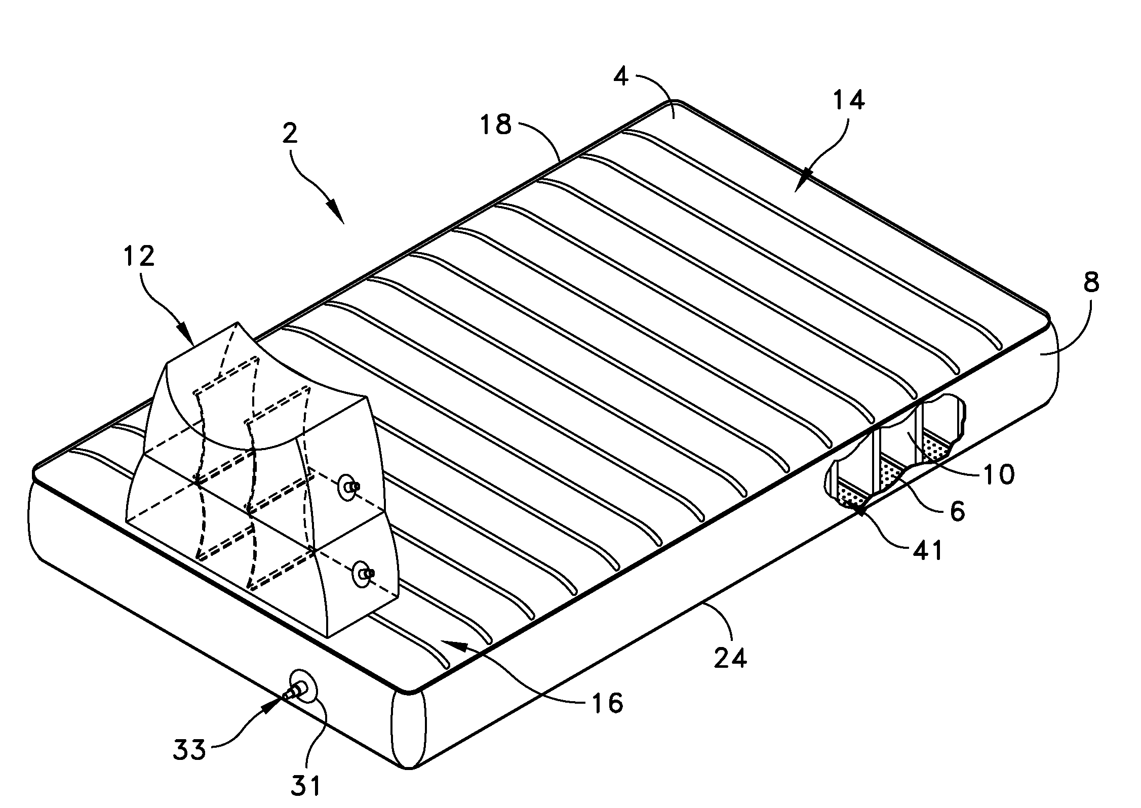
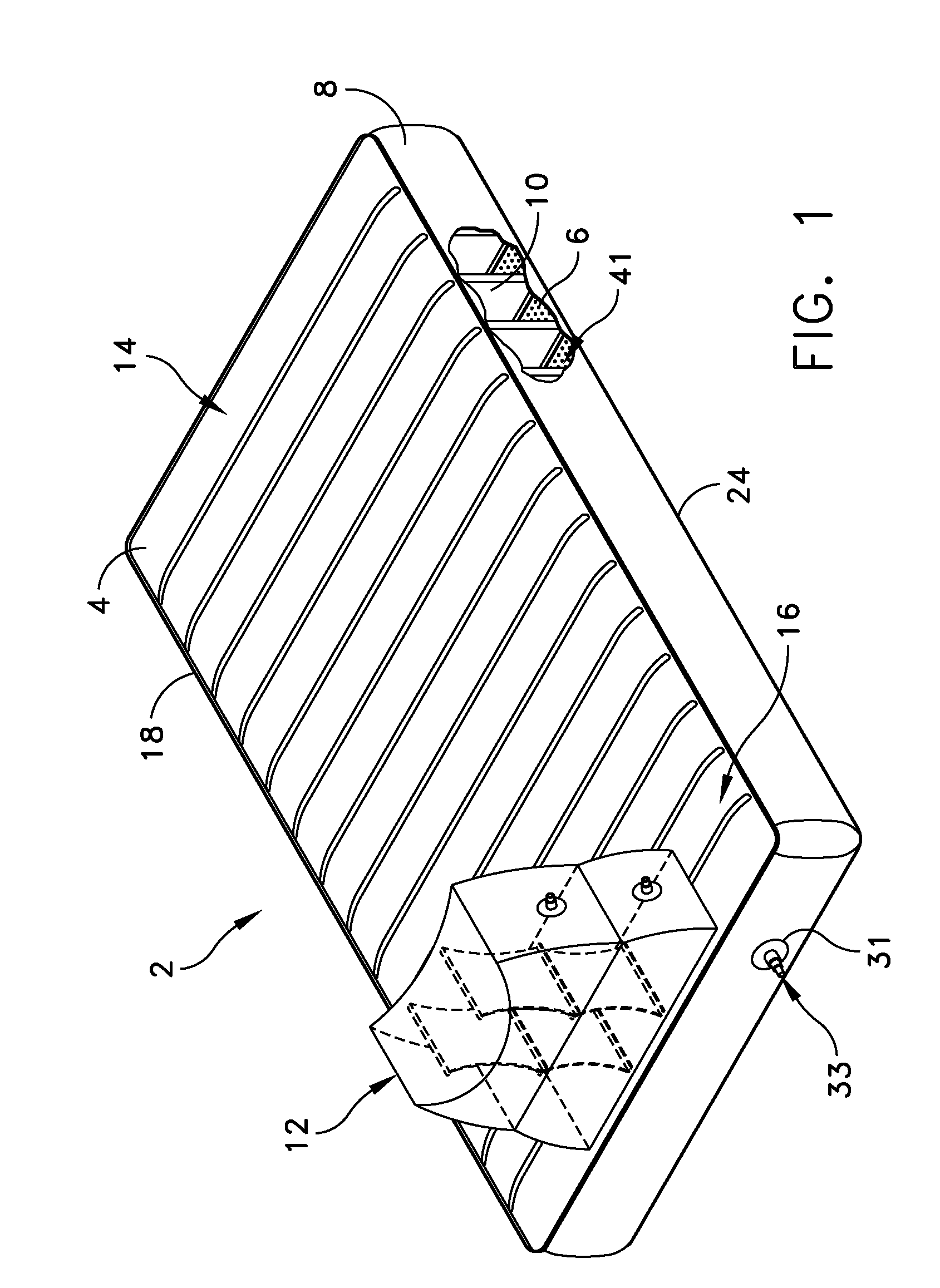
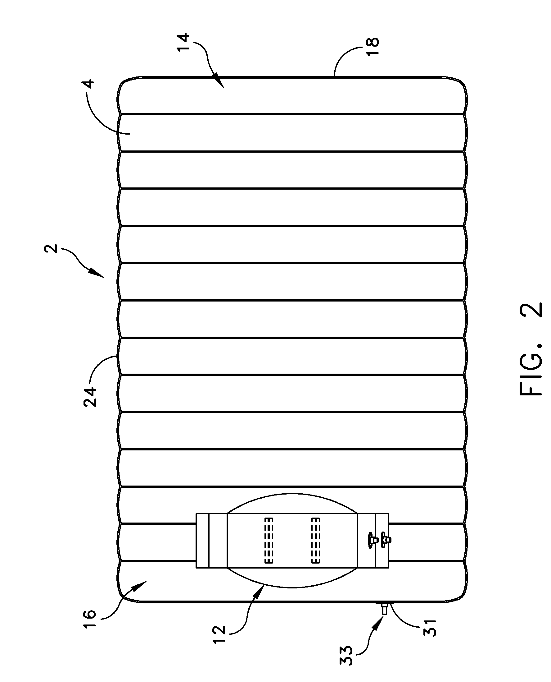
[0026]This description of preferred embodiments is intended to be read in connection with the accompanying drawings, which are to be considered part of the entire written description of this invention. The drawing figures are not necessarily to scale and certain features of the invention may be shown exaggerated in scale or in somewhat schematic form in the interest of clarity and conciseness. In the description, relative terms such as “horizontal,”“vertical,”“up,”“down,”“top” and “bottom” as well as derivatives thereof (e.g., “horizontally,”“downwardly,”“upwardly,” etc.) should be construed to refer to the orientation as then described or as shown in the drawing figure under discussion. These relative terms are for convenience of description and normally are not intended to require a particular orientation. Terms including “inwardly” versus “outwardly,”“longitudinal” versus “lateral” and the like are to be interpreted relative to one another or relative to an axis of elongation, or...


PUM


Abstract

An inflatable mattress is provided that includes a top panel having a top surface, and a bottom panel having a plurality of perforations defined therethrough. The bottom panel is sealingly assembled to the top panel. An inflatable foot rest is attached to the top surface of the top panel and is suitable for raising at least one leg of a patient when the patient is lying upon the top panel.

Description

[0001]This application claims priority from, and the benefit of U.S. provisional patent application Ser. No. 61 / 159,969, filed Mar. 13, 2009, entitled TRANSFER MATTRESS WITH INFLATABLE FOOT REST, which is incorporated herein by reference.FIELD OF THE INVENTION[0002]The present invention generally relates to air mattresses, and more particularly to air mattresses with an inflatable foot rest for elevating a patient's legs.BACKGROUND OF THE INVENTION[0003]It is well known in the medical arts that some procedures require the patient's lower body to be elevated. In some instances, the procedure may require the elevation of the patient's lower body for a time. For example, constant elevation of a patient's lower body may relieve symptoms associated with swelling or bleeding in the lower extremities. In another example, it may be desirable to keep a patient's legs elevated and stabilized during transport between examination rooms. In yet another example, the elevation of the lower body wo...

Claims


Application Information

Patent Timeline
IPC IPC(8): A61G7/00A47C27/08A47C27/10A47C20/04
CPCA61G7/0755A61G7/1021A47C20/021A61G7/1028A61G7/1098A61G7/1026
Inventor DAVIS, DAVID T.
Owner D T DAVIS ENTERPRISES LTD D B A HOVERTECH INT
Learn More