
Steerable truck for a railway car, a railway car, and an articulated car

a technology for railway cars and trucks, which is applied in the direction of self-adjusting wheel axles, rail engagement elements, transportation and packaging, etc., can solve the problems of insufficient difference in rear wheelsets, inability of railway cars to smoothly travel along curved tracks, and inability to develop longitudinal creep force fvc, etc., to achieve excellent travel ability and low cost

Inactive Publication Date: 2010-09-16
NIPPON STEEL CORP
View PDF7 Cites 16 Cited by
  • Summary
  • Abstract
  • Description
  • Claims
  • Application Information

AI Technical Summary

Benefits of technology

[0031]According to the present invention, a steerable truck for a railway car which has excellent ability to travel on a curved track and which can actually be realized because it can be carried out simply and at low cost, and a railway car and articulated cars having this steerable truck can be providedBRIEF EXPLANATION OF THE DRAWINGS
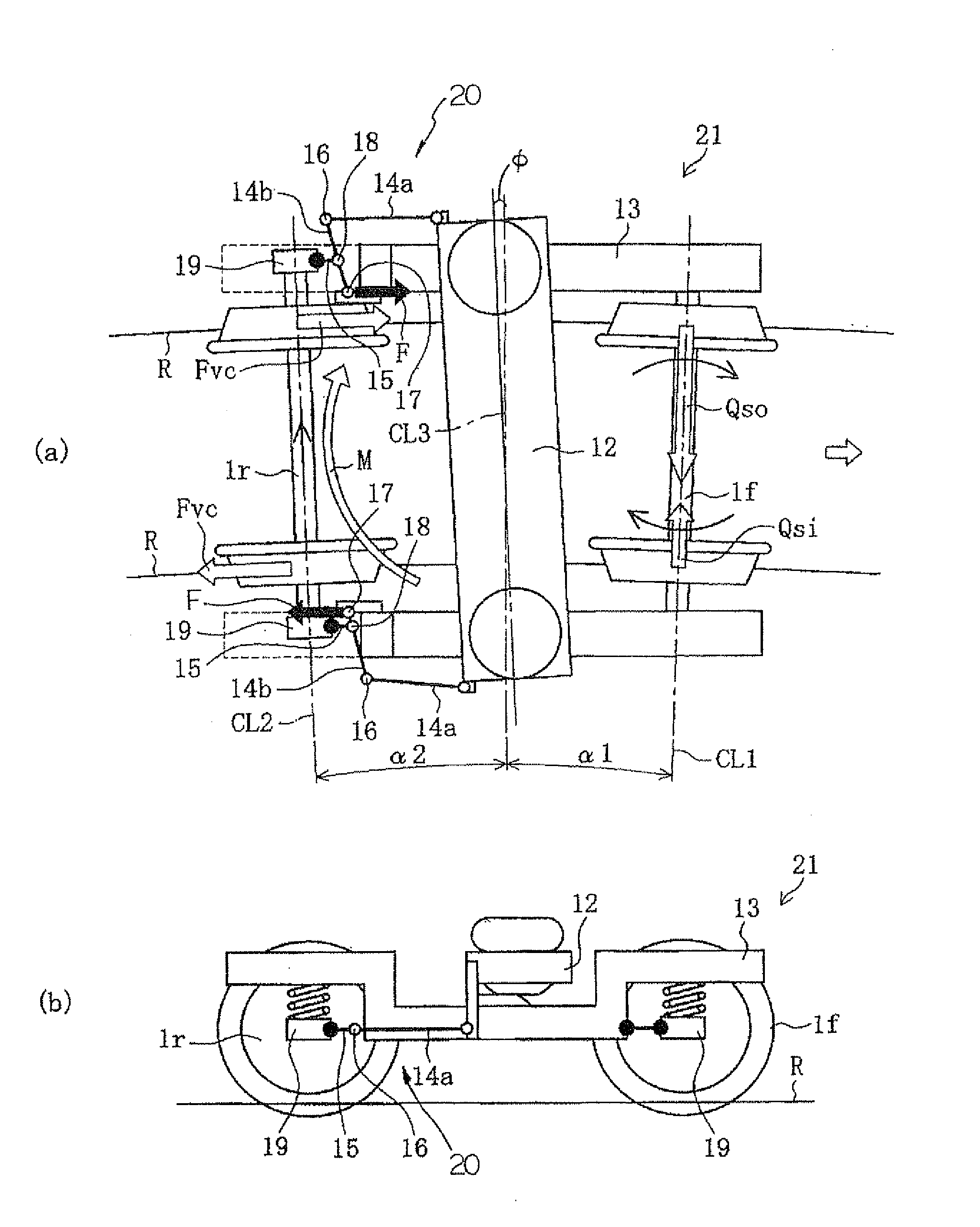
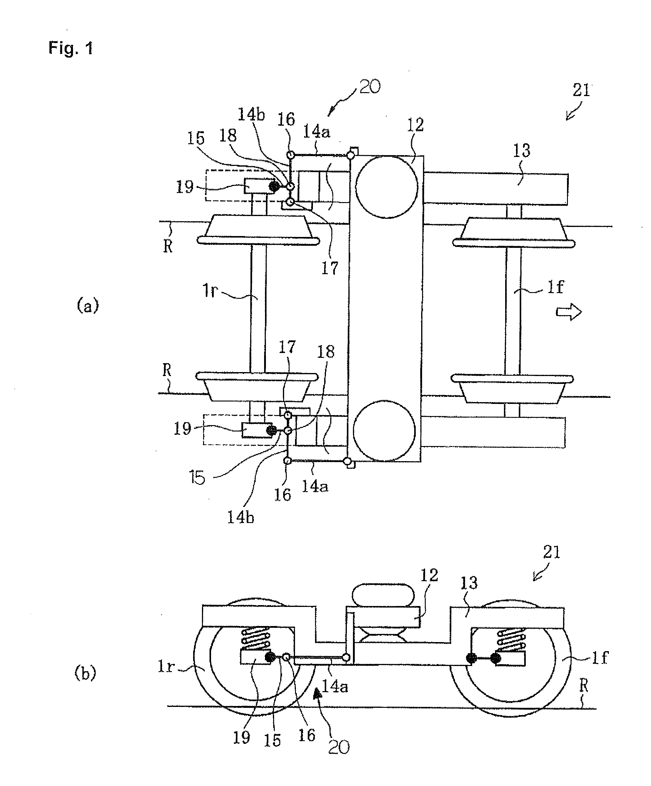
[0032]FIG. 1 is an explanatory view schematically showing the structure of a first example of a steerable truck according to the present invention (an example in which only the rear wheelset is controlled), FIG. 1(a) being a plan view and FIG. 1(b) being a side view.
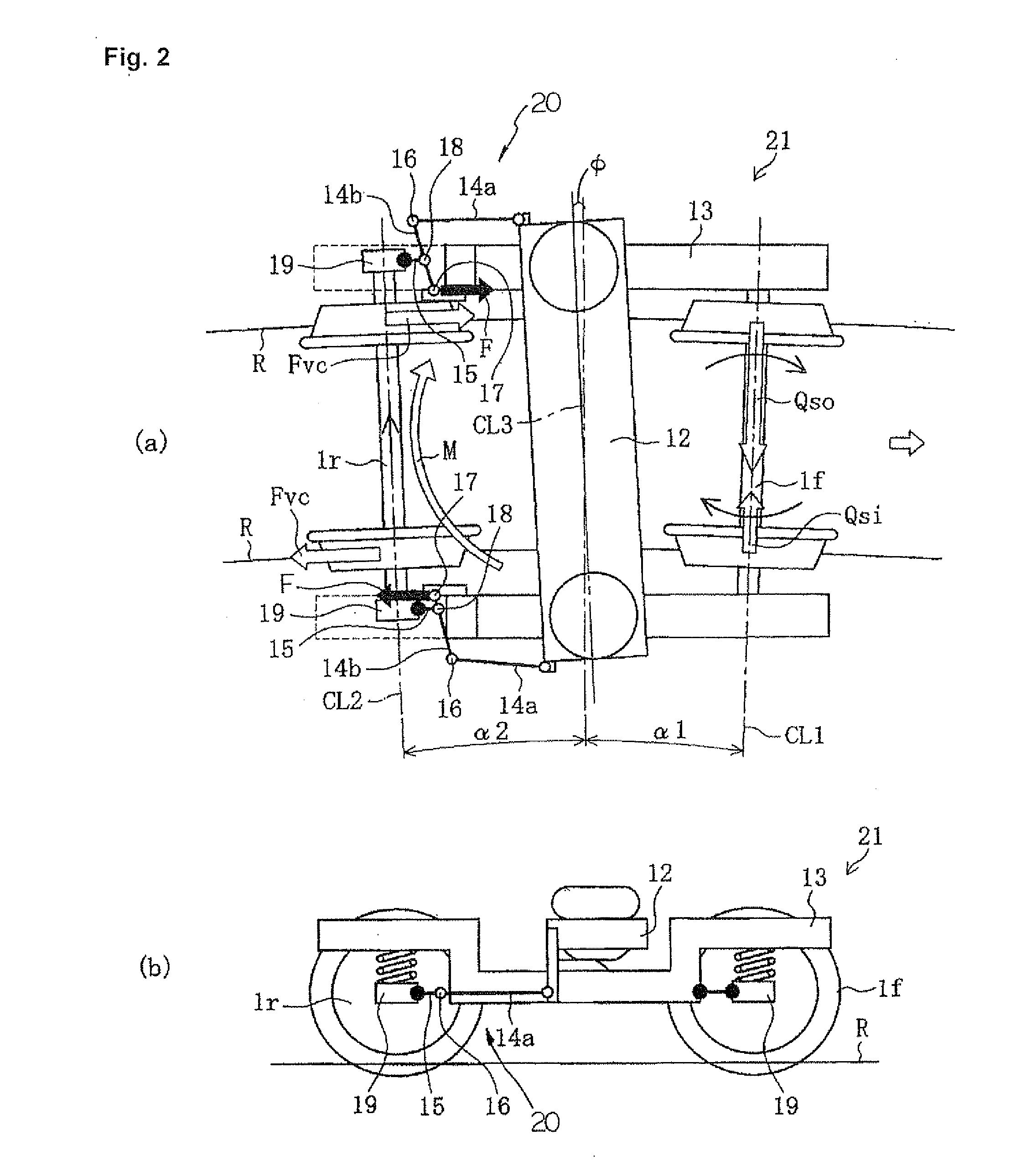
[0033]FIG. 2 is an explanatory view illustrating the behavior of the steerable truck according to the present invention shown in FIG. 1 when traveling along a curved track.
[0034]FIG. 3 is an explanatory view schematically showing the structure of a second example of a steerable truck according to the present invention (an example in which the lever ratios of steering levers vary), FIG. 3(a) being a plan view, and FIGS. 3(b)-3(d) being side views, FIG. 3(b) showing the case in which the lever ratios of a steering levers are the same, FIG. 3(c) showing the case in which the lever ratio of a steering lever is greater for the rear wheelset, and FIG. 3(d) showing the case in which only the rear wheelset is steered.
[0035]FIG. 4 is an explanatory view schematically showing the structure of a third example of a steerable truck according to the present invention (an example in which the stiffness of the steering links is varied), FIG. 4(a) being a plan view and FIG. 4(b) being a side view.
[0036]FIG. 5 is an explanatory view schematically showing the structure of a fourth example of a steerable truck according to the present invention (an example in which the location of the points where the steering links apply a force is varied), FIG. 5(a) being a plan view and FIG. 5(b) being a side view.

Problems solved by technology

Improving the ability of a railway car to smoothly travel along a curved track is and has been an important technical problem.
However, since a sufficient difference between the rolling radius of the left and right wheels 5 is not obtained, the radius difference in the rear wheelset is insufficient and causes a longitudinal creep force Fvc to develop.
Therefore, the apparatus becomes complicated and costly.

Method used


Image

  • Steerable truck for a railway car, a railway car, and an articulated car
  • Steerable truck for a railway car, a railway car, and an articulated car
  • Steerable truck for a railway car, a railway car, and an articulated car

Examples


Embodiment Construction

[0048]Below, the best mode for carrying out the present invention will be explained while referring to the attached drawings.

[0049]In the following explanation, an example will be given of the case in which control of the steering angle of the rear wheelset by a truck frame steering unit according to the present invention is carried out by a link mechanism mounted on the truck frame. In addition, in the following explanation, the same components as the components in above-described FIGS. 14-16 are affixed with the same symbols, so a repeated explanation thereof will be omitted.

[0050]FIG. 1 is an explanatory view schematically showing the structure of a first example of a steerable truck 21 according to the present invention, FIG. 1(a) being a plan view and FIG. 1(b) being a side view.

[0051]This steerable truck 21 has a truck frame steering unit 20 mounted only on the rear wheelset 1r.

[0052]The rear wheelset 1r in this steerable truck 21 is connected to a bolster 12 which is mounted...


PUM


Abstract

A steerable truck for a railway car is provided with a truck frame that is steered so as to be aligned with the tangential direction of a curved track by controlling only the steering angle of a rear wheelset. During travel along a curved track, the steering angle, which is the angle in a horizontal plane of the centerline of the rear wheelset with respect to an imaginary straight line connecting the center of the truck frame and the center of the curved track, is larger than the steering angle which is the angle formed between the imaginary straight line and the centerline of the front wheelset. As a result, a steerable truck for a railway car which has excellent ability to travel along a curve and which can be actually realized simply and at a low cost is provided.

Description

TECHNICAL FIELD[0001]This invention relates to a steerable truck for a railway car and a railway car and an articulated car equipped with this steerable truck.BACKGROUND ART[0002]Improving the ability of a railway car to smoothly travel along a curved track is and has been an important technical problem. There is a strong desire for an increased ability of a railway car to travel along curves, particularly for railway cars traveling along sharp curves in suburban railways such as underground railways.[0003]FIG. 14 is an explanatory view schematically showing the behavior of a conventional truck 3 in which the wheels are not steered with respect to a truck frame 2 when traveling along a curved track 4. The truck frame 2 which is traveling along a curved track 4, the wheelset 1f positioned to the front in the direction of travel (referred to in this description as the front wheelset) and the wheelset 1r positioned to the rear in the direction of travel (referred to in this description...

Claims


Application Information

Patent Timeline
IPC IPC(8): B61F3/12B61F5/38
CPCB61F5/44
Inventor KIKKO, SATOSHINAKAI, TAKUJITSUTSUI, YUJIN
Owner NIPPON STEEL CORP
Learn More