
Methods for Cryptographic Identification of Interchangeable Parts for Surgical Instruments

a technology of interchangeable parts and cryptographic identification, applied in the field of surgical instruments, can solve problems such as reducing manufacturing difficulty

Active Publication Date: 2010-09-16
CILAG GMBH INT
View PDF70 Cites 724 Cited by
  • Summary
  • Abstract
  • Description
  • Claims
  • Application Information

AI Technical Summary

Benefits of technology

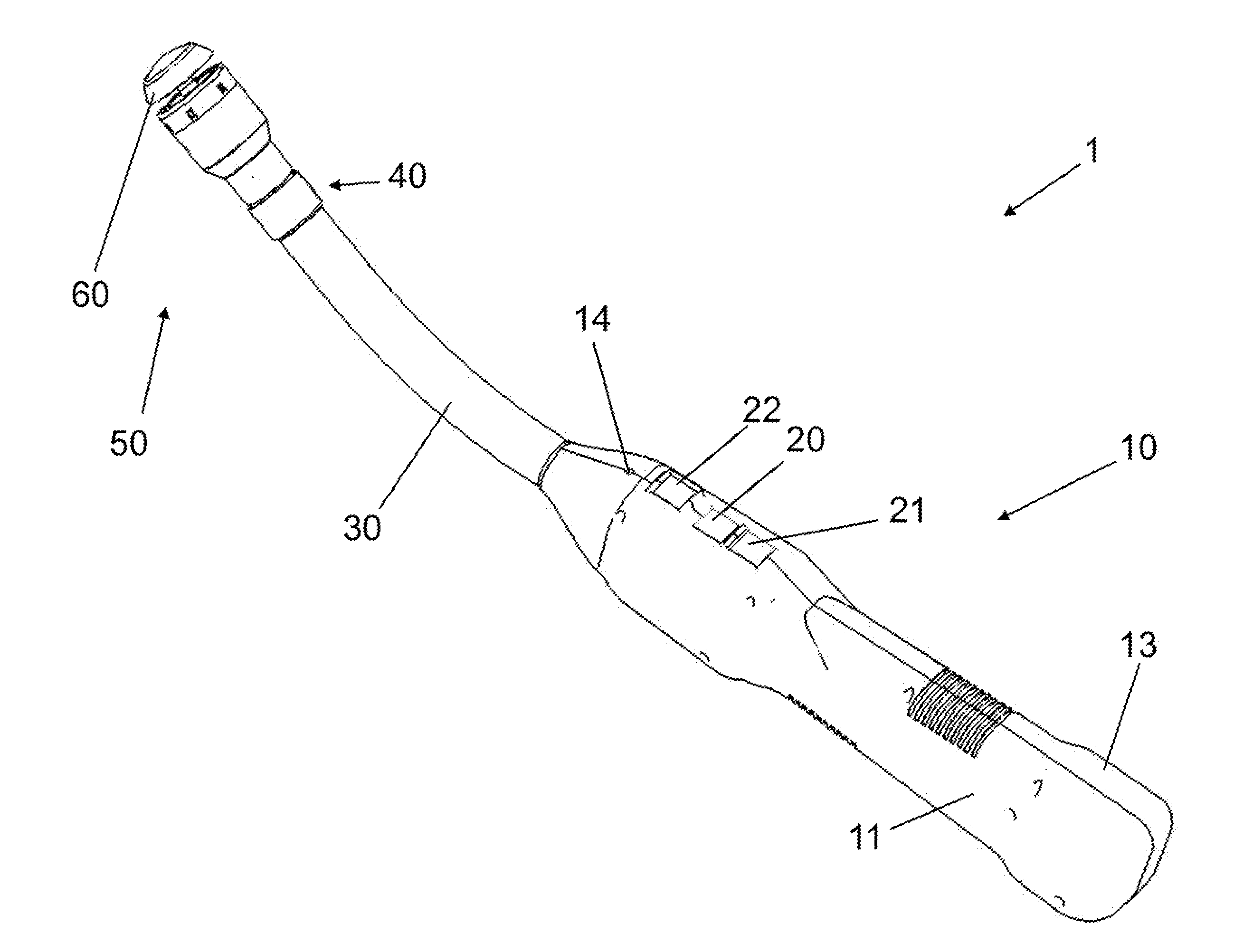
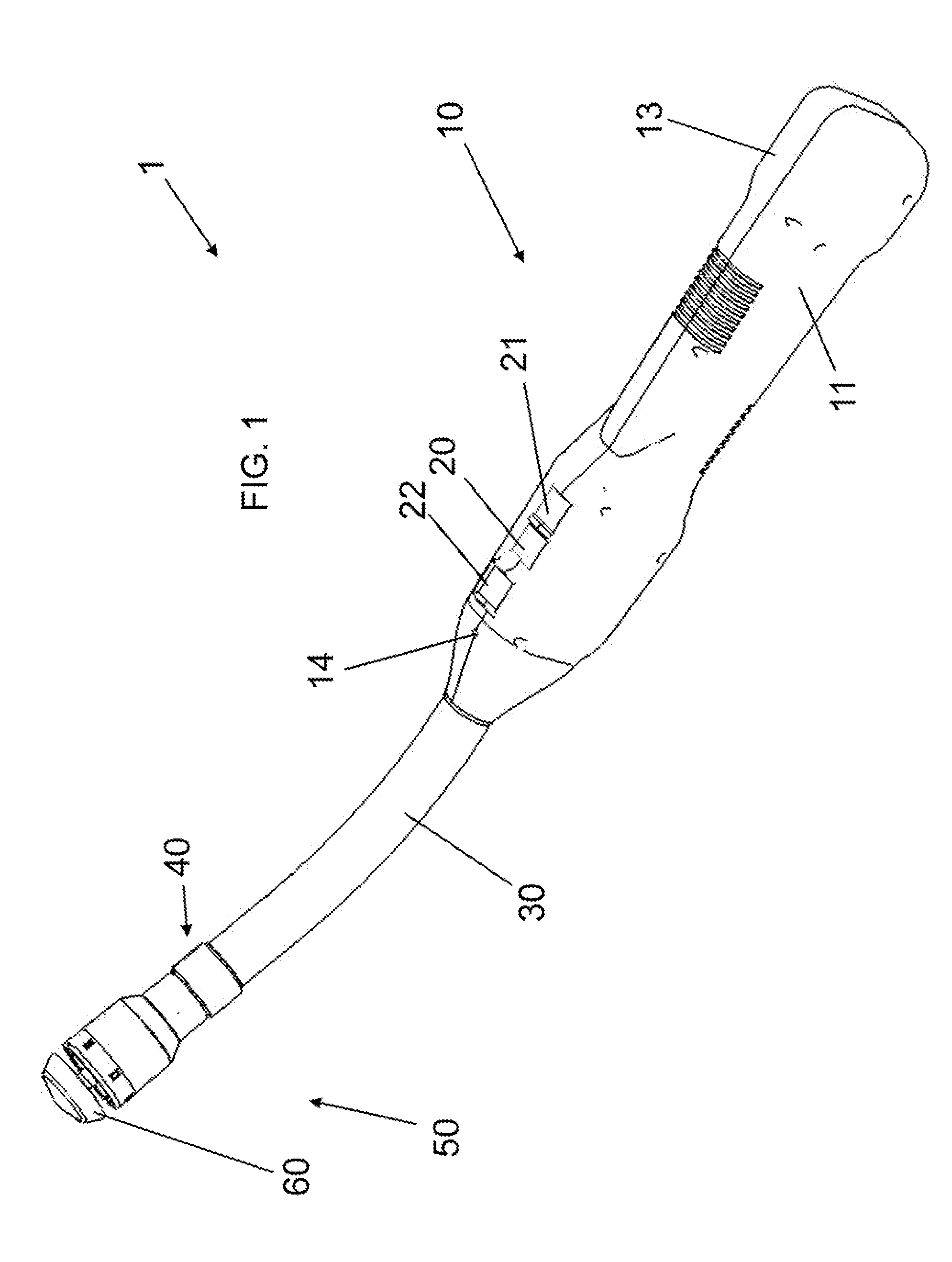
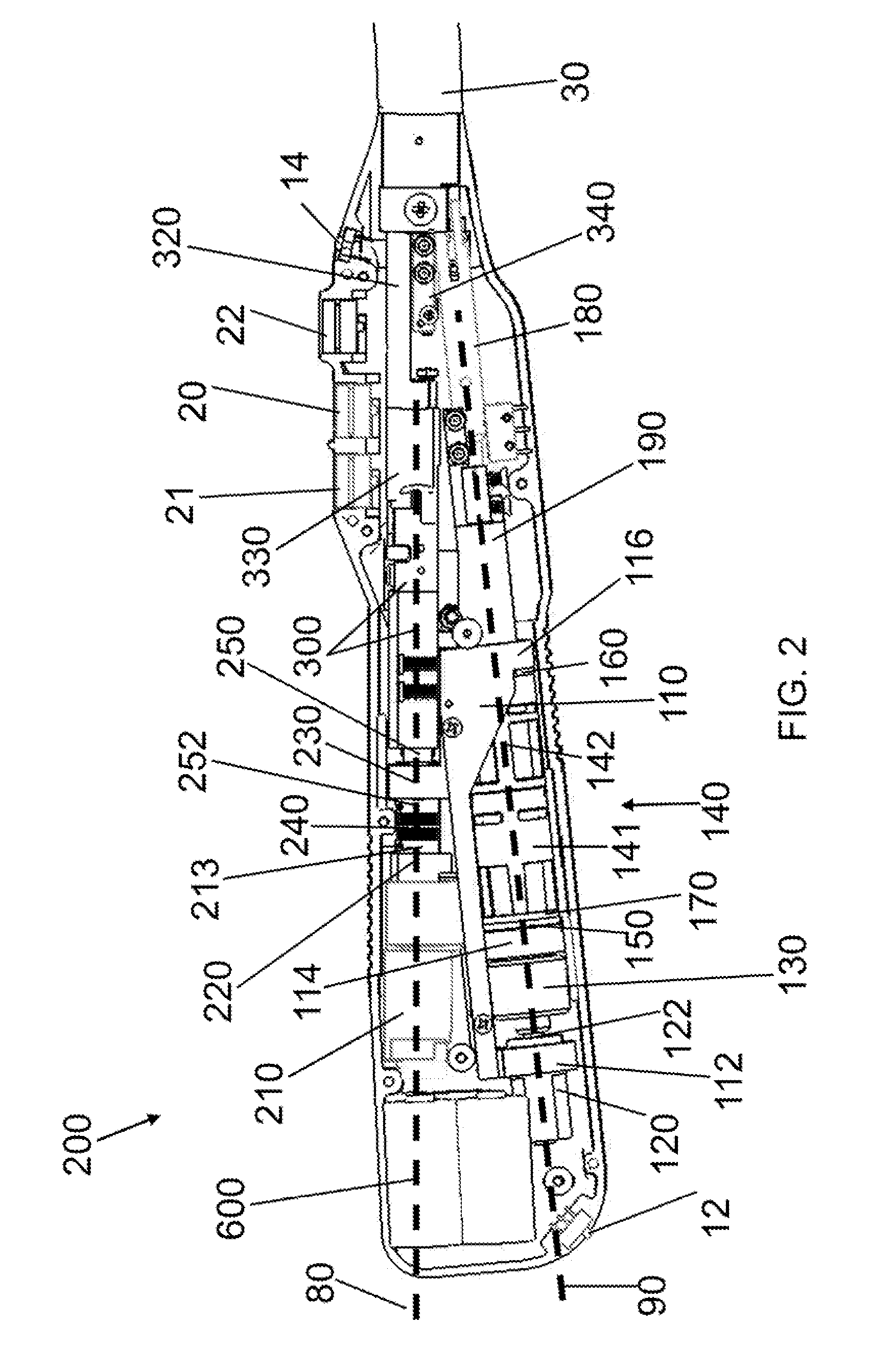
[0009]The invention overcomes the above-noted and other deficiencies of the prior art by providing an electrically self-powered surgical device that uses the self-power to effect a medical procedure. For example, in a linear endocutter, the electric on-board power can position an anvil and stapler cartridge with respect to one another about tissue to be stapled and / or cut, and, after closing the anvil and stapler cartridge with respect to one another, firing and securing the staples at the tissue (and / or cutting the tissue). Further, the electrically self-powered surgical device can indicate to the user a user-pre-defined level of compressive force being imparted upon the tissue prior to firing the staples. The present invention also provides methods for operating the electric surgical stapling device to staple when optimal tissue compression (OTC) exists. Also provided is a cryptographic identification of disposable parts, such as the staple cartridge. Further provided is a manual release device that allows recovery from a partial actuation or a jam.
[0010]An offset-axis configuration for the two anvil and staple firing sub-assemblies creates a device that can be sized to comfortably fit into a user's hand. It also decreases manufacturing difficulty by removing previously required nested (co-axial) hollow shafts. With the axis of the anvil sub-assembly being offset from the staple firing sub-assembly, the length of the threaded rod for extending and retracting the anvil can be decreased by approximately two inches, thereby saving in manufacturing cost and generating a shorter longitudinal profile.

Problems solved by technology

It also decreases manufacturing difficulty by removing previously required nested (co-axial) hollow shafts.

Method used


Image

  • Methods for Cryptographic Identification of Interchangeable Parts for Surgical Instruments
  • Methods for Cryptographic Identification of Interchangeable Parts for Surgical Instruments
  • Methods for Cryptographic Identification of Interchangeable Parts for Surgical Instruments

Examples


Embodiment Construction

[0105]As required, detailed embodiments of the present invention are disclosed herein; however, it is to be understood that the disclosed embodiments are merely exemplary of the invention, which can be embodied in various forms. Therefore, specific structural and functional details disclosed herein are not to be interpreted as limiting, but merely as a basis for the claims and as a representative basis for teaching one skilled in the art to variously employ the present invention in virtually any appropriately detailed structure. Further, the terms and phrases used herein are not intended to be limiting; but rather, to provide an understandable description of the invention. While the specification concludes with claims defining the features of the invention that are regarded as novel, it is believed that the invention will be better understood from a consideration of the following description in conjunction with the drawing figures, in which like reference numerals are carried forwar...


PUM

PropertyMeasurementUnit
lengthaaaaaaaaaa
sizeaaaaaaaaaa
sizeaaaaaaaaaa

Abstract

A method for encrypted authentication of interchangeable parts of a surgical instrument includes providing a surgical end effector at a distal end of a handle of the surgical instrument and electrically connecting an authentication controller within the handle to a receiving portion of the end effector. An interchangeable part is removably placed at the receiving portion. The interchangeable part is authenticated with the authentication controller when the interchangeable part is seated in the end effector.

Description

CROSS-REFERENCE TO RELATED APPLICATIONS[0001]This application is:[0002]a divisional application of U.S. patent application Ser. No. 12 / 034,320, filed Feb. 20, 2008 (which application claims the priority of U.S. Provisional Application Ser. No. 60 / 902,534, filed Feb. 21, 2007, and 60 / 977,489, filed Oct. 4, 2007); and[0003]a divisional application of U.S. patent application Ser. No. 12 / 245,017, filed Oct. 3, 2008 (which application claims the priority of U.S. Provisional Application Ser. No. 60 / 977,489, filed Oct. 4, 2007); and[0004]a continuation-in-part of U.S. patent application Ser. Nos. 11 / 705,246, 11 / 705,334, and 11 / 705,381, each filed Feb. 12, 2007 (which parent applications claim the priority of U.S. Provisional Application Nos. 60 / 801,989, filed May 19, 2006, 60 / 810,272, filed Jun. 2, 2006, and 60 / 858,112, filed Nov. 9, 2006),the entire disclosures of which are all hereby incorporated herein by reference in their entireties.FIELD OF THE INVENTION[0005]The present invention li...

Claims


Application Information

Patent Timeline
Patent Type & Authority Applications(United States)
IPC IPC(8): A61B17/068H04L9/00
CPCA61B17/1114A61B17/115A61B2017/00084A61B2017/00398A61B2019/4857A61B2017/00734A61B2017/2943A61B2019/448A61B2019/465A61B2017/00473A61B90/98A61B2090/065A61B2090/08021A61B2090/0811A61B2090/0814A61B17/07207A61B17/1155A61B2017/0046A61B2017/07257A61B2017/07271A61B2017/07285H04L9/10
Inventor SMITH, KEVIN W.BALES, JR., THOMAS O.DEVILLE, DEREK DEERIVERA, CARLOSPALMER, MATTHEW A.
Owner CILAG GMBH INT
Learn More