Eureka AIR delivers breakthrough ideas for toughest innovation challenges, trusted by R&D personnel around the world.

Low cost, high performance pipe connection

a high-performance, low-cost technology, applied in the direction of hose connection, screw threaded joint, handling devices, etc., can solve the problems of lack of performance, one bad feature of failing a connection, maintaining the contact, etc., to achieve reasonable manufacturing costs and assembly ease, less efficient products, and high mechanical strength

Inactive Publication Date: 2010-09-16
RAMOS BEVERLY WATTS
View PDF20 Cites 4 Cited by
  • Summary
  • Abstract
  • Description
  • Claims
  • Application Information

AI Technical Summary

Benefits of technology

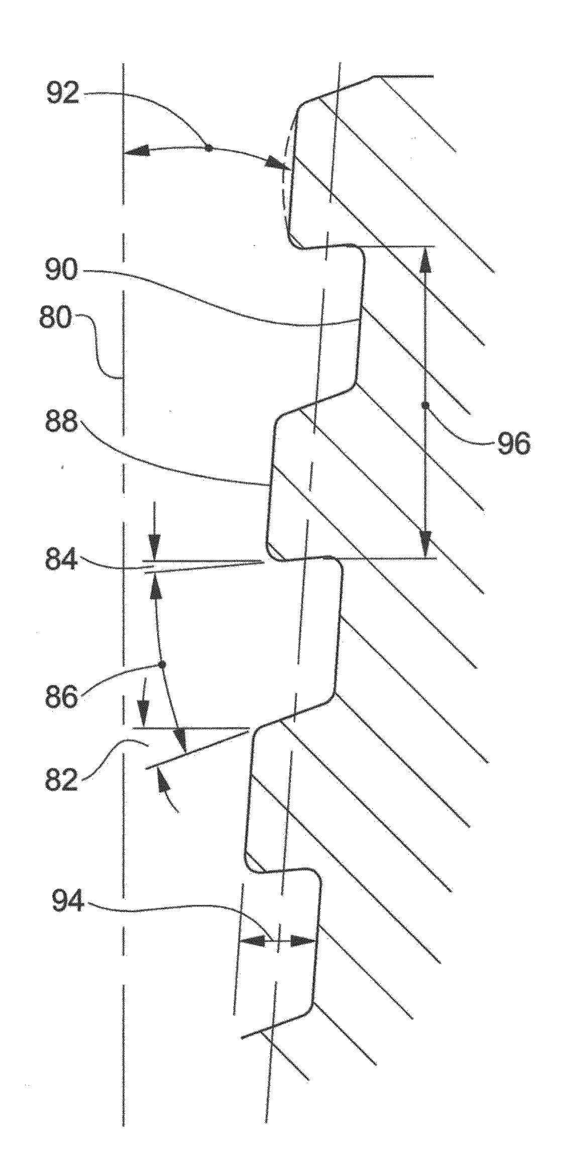
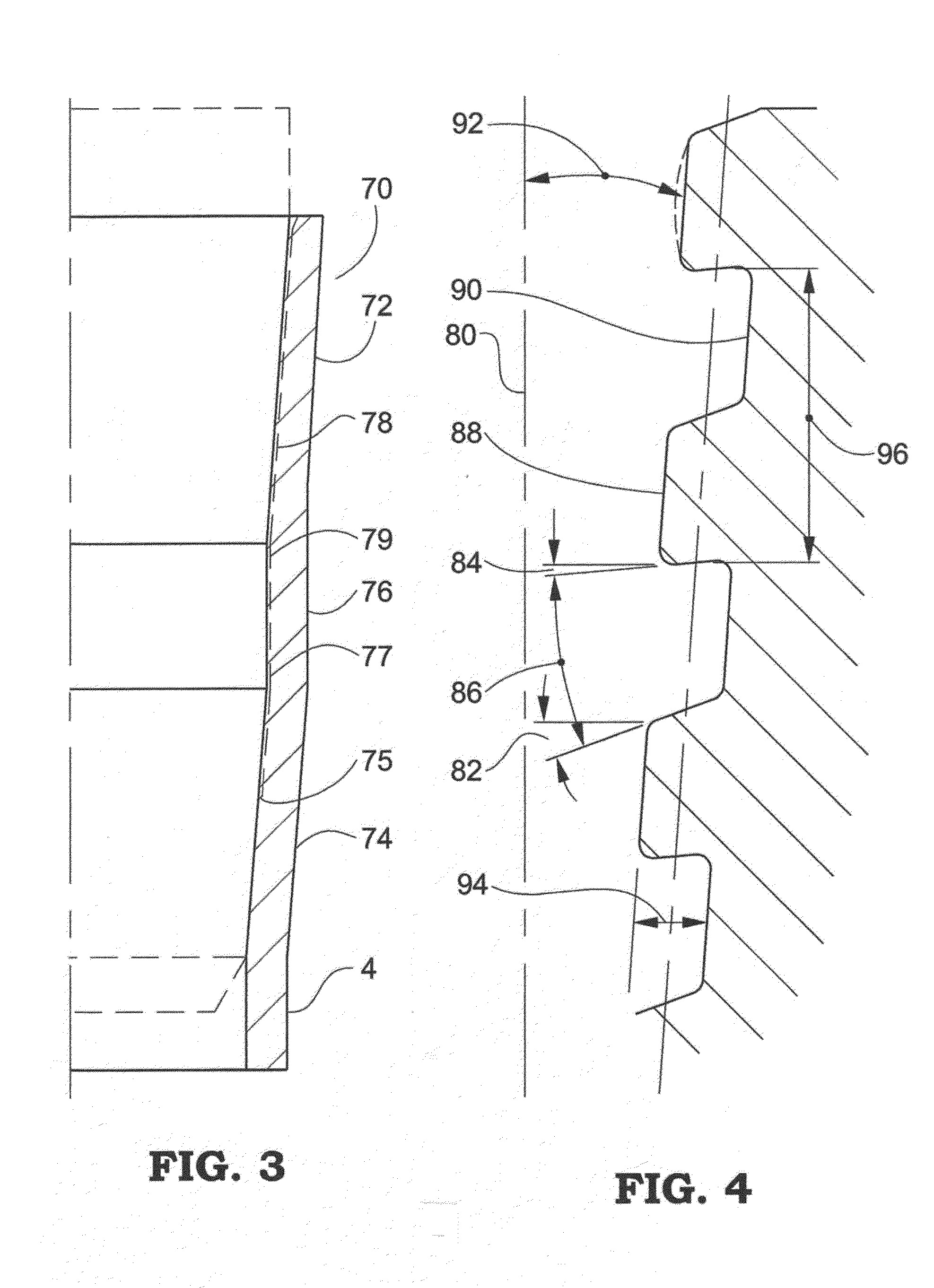
[0006]There have been many thread forms sold over the past hundred years having some good features but they often failed because they also had some poor features, and it only takes one bad feature to fail a connection. For instance, 8 round threads per API 5B, insured mating flank contact upon assembly but could not maintain that contact when in service, because the 30 degree load flank angles generated more radial force from service loads than the box and pin wall thicknesses could withstand. Conversely, API Buttress flank angles were low enough to withstand the radial forces, but thread widths were less than the gap widths between mating flanks, which precluded firm contact between mating flanks even upon assembly, as taught by my patent U.S. Pat. No. 5,428,418. Thus, for future generations of thread designers, workable limits are now disclosed: The cone angle should be not less than 4 degrees to prevent locking of pin crests between box crests and not more than 6 degrees, to allow enough threads within the pipe wall radial width to withstand rated loads; the included angle should be not less than 14 degrees to allow a root-crest gap width small enough to seal, and not more than 35 degrees so as to build sufficient pressure between mating flanks to prevent relative movement between them when urged by service forces; stab flank angles should be not more than 30 degrees to prevent thread jump-in and not less than minus 15 degrees to permit reasonable

Problems solved by technology

There have been many thread forms sold over the past hundred years having some good features but they often failed because they also had some poor features, and it only takes one bad feature to fail a connection.
For instance, 8 round threads per API 5B, insured mating flank contact upon assembly but could not maintain that contact when in service, because the 30 degree load flank angles generated more radial force from service loads than the box and pin wall thicknesses could withstand.
1. A preferred thread form is de

Method used


Image

  • Low cost, high performance pipe connection
  • Low cost, high performance pipe connection
  • Low cost, high performance pipe connection

Examples


Embodiment Construction

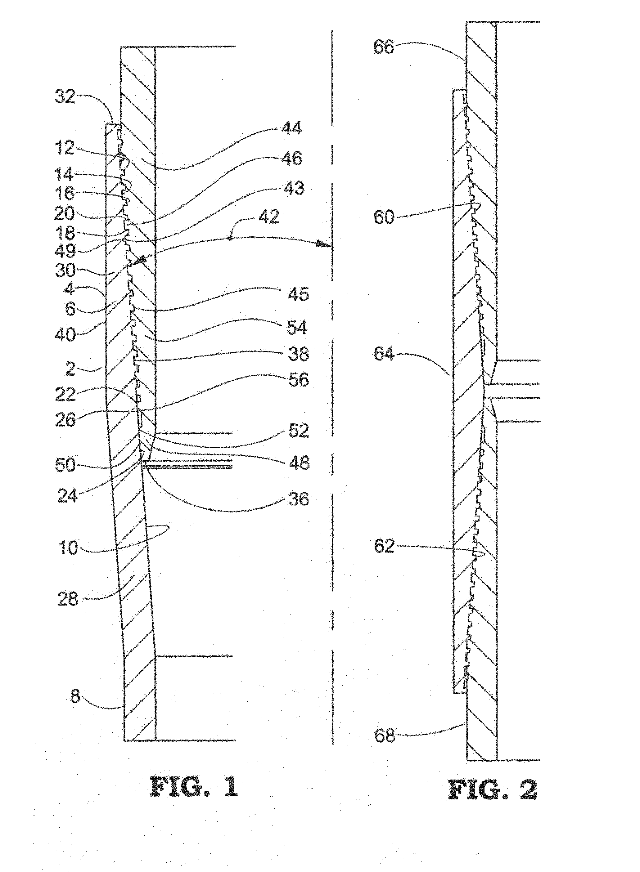
[0035]FIG. 1 depicts Pipe Connection (2) comprising: box (4) formed within swage (6) on the end of pipe joint (8), the swage having inner surface as swaged (10), internal tapered box thread (12) thread root (14), thread crest (16), stab flank (18), load flank (20) least diameter of the box root at (22), box seat (24), largest diameter (26) of the box seat, swage neck (28), box wall (30), box face (32), run-out thread (38) whose crest is of same diameter as least diameter of box root (22), box outer diameter (40), and thread cone angle (42).

[0036]FIG. 1 also depicts pin (44) comprising: pin face (36), tapered external pin thread (46) that mates with the box thread; pin nose (48); pin thread crest (43), pin thread root (45), pin nose crest (50) that seals in cooperation with the box seat; pin nose crest portion of largest diameter (52); pin wall (54); least diameter (56) of the pin root whose width may comprise a circular groove, but not necessarily. If grooved, then the first thread ...


PUM


Abstract

A low cost threaded pipe connection for virtually any service is provided, that has selectively, unique sealing threads for general use that can be supplemented with a pin nose seal when specified by the user.

Description

[0001]This application claims the priority date of Provisional Patent Application 61 / 191,613 filed Sep. 10, 2008 which incorporates by reference, the subject matter of Provisional Patent 61 / 128,098.TECHNICAL FIELD[0002]My invention may be used in piping systems that require high strength and safe sealing capability such as for high pressure oil and gas wells and chemical plants, but its simplicity and low cost makes it applicable to non-critical services also. For purposes of this application, the following definitions will apply:1. Pipe connection=A first tubular member having tapered external pipe threads (the pin) and a second tubular member having tapered internal threads (the box) for connecting and sealing them together.2. Stab flank=The thread flank facing generally toward the end of the tubular member.3. Load flank=The thread flank facing generally away from the end of the tubular member.4. Thread Crest=The maximum diameter thread surface between flanks of a pin thread, or t...

Claims


Application Information

Patent Timeline
IPC IPC(8): F16L25/10B21K27/06
CPCF16L15/001E21B17/042F16L15/06F16L15/002
Inventor WATTS, JOHN D.
Owner RAMOS BEVERLY WATTS
Why Eureka
Eureka Blog
Learn More