
Sideview Vision System Displaying A View Dependent Upon Transmission Selector

a transmission selector and vision system technology, applied in the field of sideview vision systems, can solve the problems of limited field of view, inability to provide the driver with a comprehensive view, and the mirror may not be optimally adjusted for backing up

Inactive Publication Date: 2010-09-16
DELPHI TECH INC
View PDF10 Cites 31 Cited by
  • Summary
  • Abstract
  • Description
  • Claims
  • Application Information

AI Technical Summary

Benefits of technology

This patent describes a sideview vision system for a vehicle that can capture an image of the area behind the vehicle and display it to the driver. The system can switch between two different views based on the position of a transmission selector. The first view is shown when the selector is in the first position, and the second view is shown when the selector is in the second position. This allows the driver to have a clear view of the area behind the vehicle at different angles and positions. The technical effect of this invention is to improve the driver's visibility and safety while driving.

Problems solved by technology

However, conventional sideview mirrors have a limited field of view and do not provide the driver with a comprehensive view of the area, so objects in portions of the area alongside and behind a vehicle may not be seen by the driver.
For example, if the mirror position is adjusted by the driver to be optimum for traveling in a forward direction where the driver is observing an adjacent traffic lane rearward the vehicle, then the mirror may not be optimally adjusted for backing up where the driver needs to see the area near the rear wheel and rear bumper.
However, this provision has an undesirable time response delay due to the mechanical motion, and adds undesirable cost and complexity to the mirror assembly.
As with sideview mirrors, mechanically changing the aimed direction of a camera using a mechanical position control system has the same undesirable cost, complexity, and time response delay problems as the motorized mirrors.

Method used


Image

  • Sideview Vision System Displaying A View Dependent Upon Transmission Selector
  • Sideview Vision System Displaying A View Dependent Upon Transmission Selector
  • Sideview Vision System Displaying A View Dependent Upon Transmission Selector

Examples


Embodiment Construction

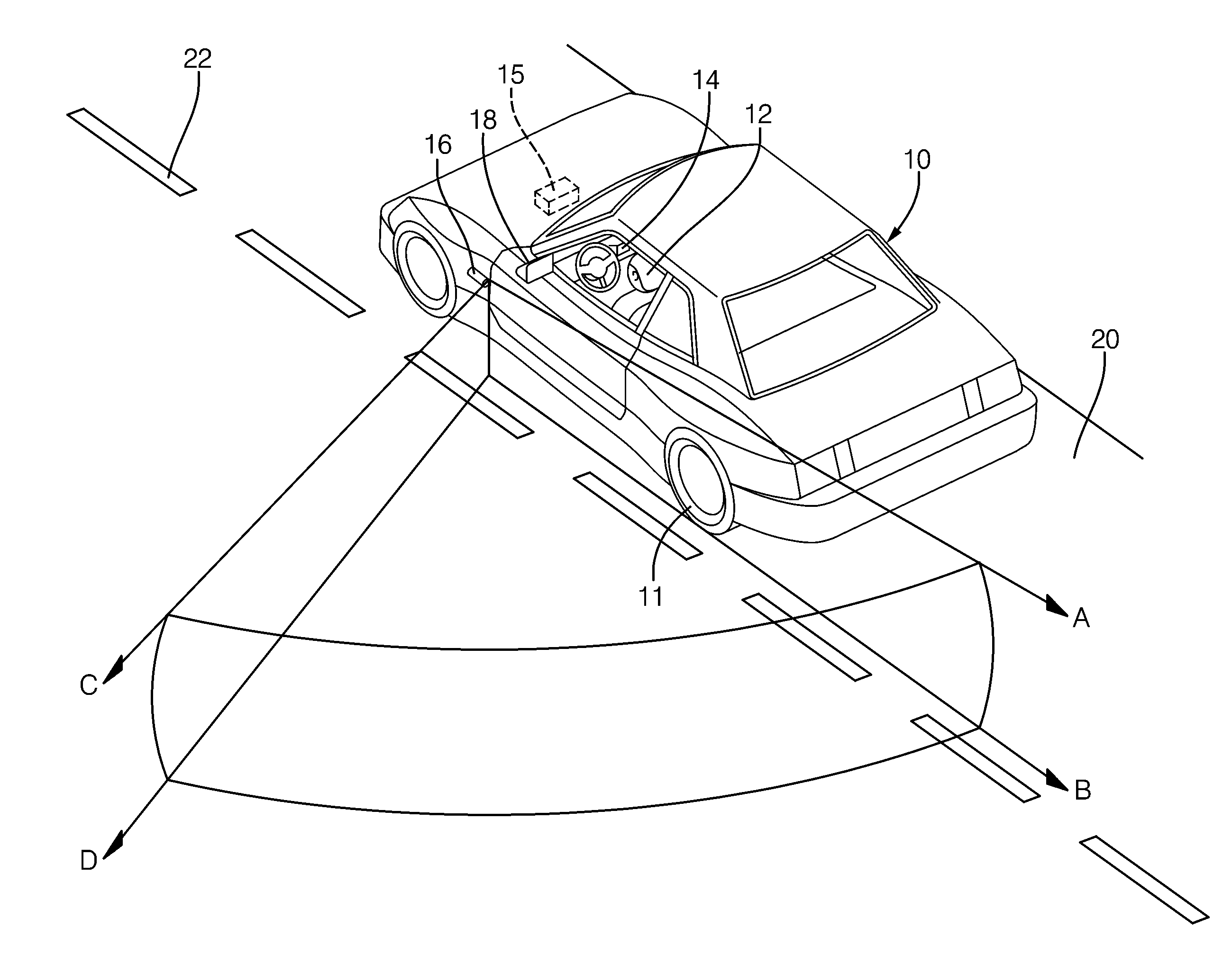
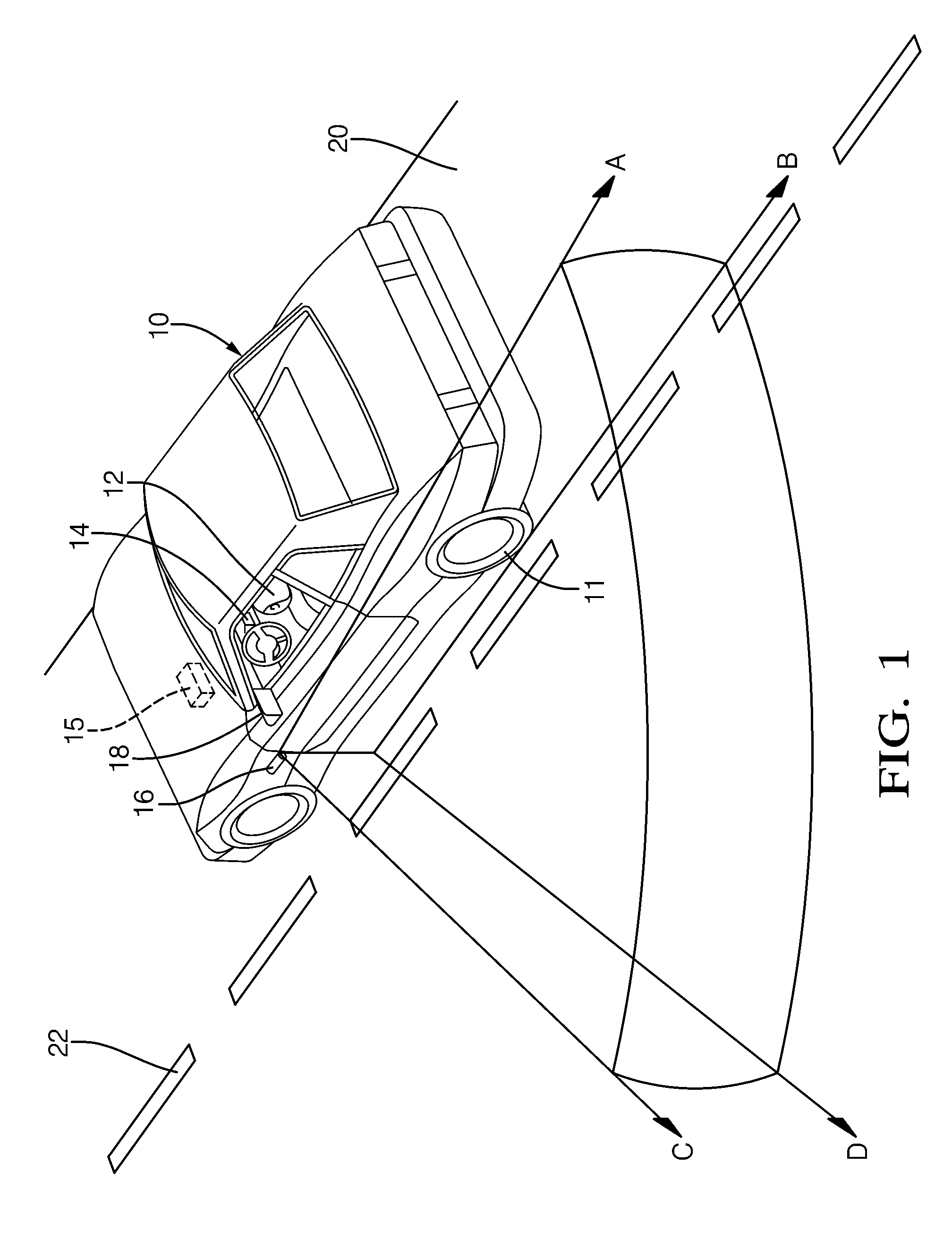
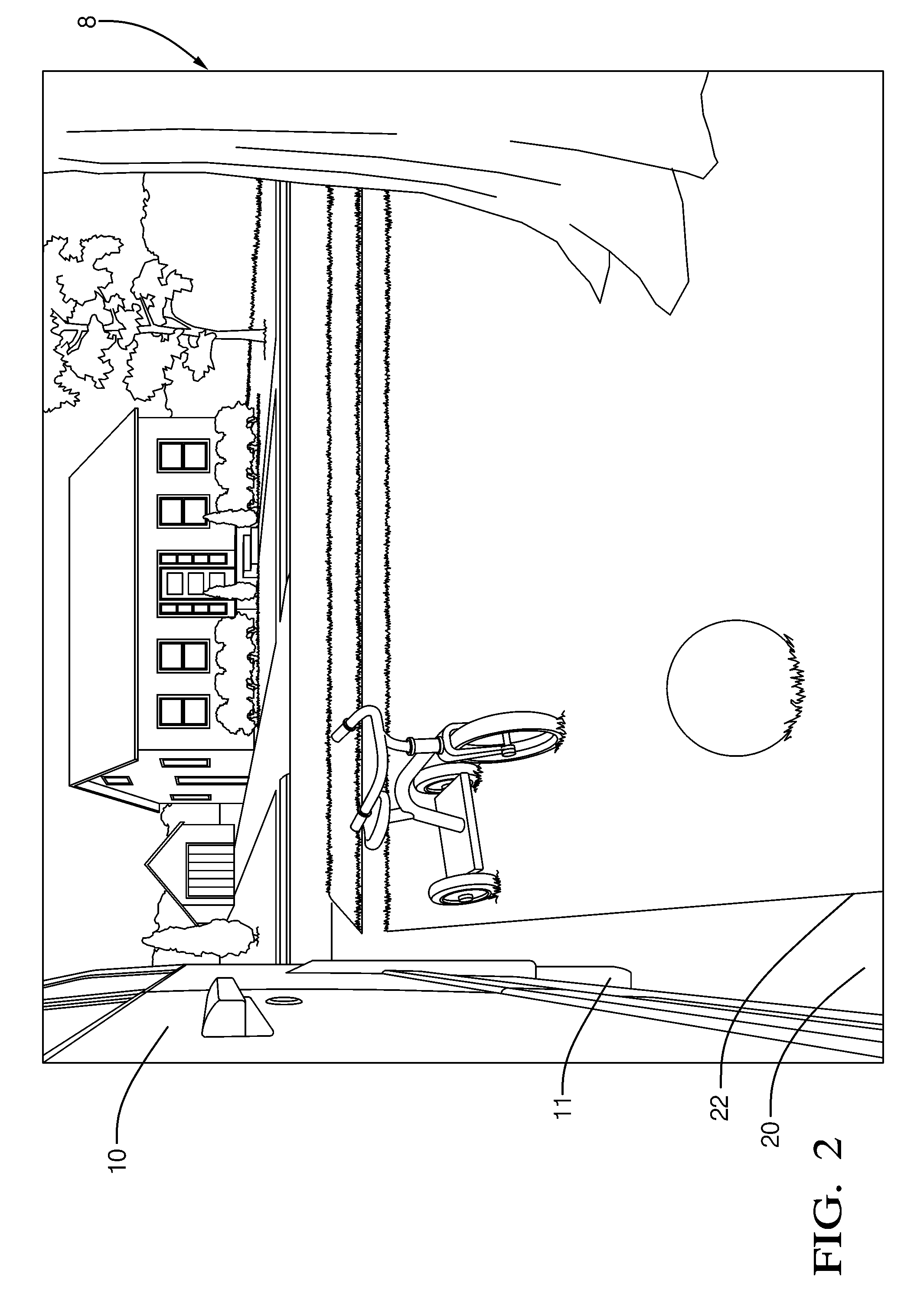
[0021]In accordance with a preferred embodiment of this invention, FIG. 1 shows a vehicle 10 operated by a driver 12 along a roadway 20 having a region adjacent vehicle 10. Roadway 20 includes lane markers, referred to herein as boundary 22. The roadway could be a multi-lane highway, where the adjacent region is a traffic lane where other vehicles travel in the same direction as vehicle 10, or a two-lane road, where the adjacent region is a traffic lane where other vehicles travel in the opposite direction. Alternatively, the vehicle could be parallel parked on a shoulder of a roadway and the region is a traffic lane, or the vehicle could be in a driveway, where the region is a lawn boarding the driveway. The vehicle has a conventional sideview mirror 18 to assist the driver with observing an area alongside and extending rearward the vehicle and identifying objects adjacent to the vehicle. In accordance with this invention, vehicle 10 is also equipped with a sideview vision system t...


PUM


Abstract

A sideview vision system in a vehicle and a method for operating the system. The sideview vision system has a camera fixedly mounted to the vehicle for capturing an image alongside and extending rearward the vehicle, and a display for displaying a view to a driver of the vehicle. The method includes capturing an image using the camera, the image having a first portion and a second portion different from the first portion, displaying a first view corresponding to the first portion in response to the vehicle transmission being in a forward gear, and displaying a second view corresponding to the second portion in response to the transmission being in a reverse gear.

Description

TECHNICAL FIELD OF INVENTION[0001]The invention relates to sideview vision systems for vehicles that include a camera and a display viewable by a driver. More particularly, this invention relates to such sideview vision system wherein the portion of an image from the camera that is displayed is dependent upon the transmission selector position, for example, whether the vehicle is in a forward gear or in a reverse gear.BACKGROUND OF INVENTION[0002]It is known to provide sideview mirrors on vehicles to assist a driver with viewing an area alongside and behind a vehicle. Mirrors are useful for assisting the driver in seeing obstacles prior to changing lanes or backing up, where the obstacles might otherwise collide with the vehicle. However, conventional sideview mirrors have a limited field of view and do not provide the driver with a comprehensive view of the area, so objects in portions of the area alongside and behind a vehicle may not be seen by the driver. These portions where un...

Claims


Application Information

Patent Timeline
Patent Type & Authority Applications(United States)
IPC IPC(8): H04N7/18
CPCB60R1/00B60R2300/302B60R2300/806B60R2300/70B60R2300/8026B60R2300/306B60R1/28B60R1/26
Inventor GARNER, TIMOTHY D.
Owner DELPHI TECH INC
Learn More