Deferred control of surrogate key generation in a distributed processing architecture

a distributed processing and surrogate key technology, applied in the field of event processing, can solve problems such as inability to work normally, inability to perform incorrect data correlation, and indeterminate or incorrect calculation,

Inactive Publication Date: 2010-09-16
AVAYA INC
View PDF22 Cites 8 Cited by
  • Summary
  • Abstract
  • Description
  • Claims
  • Application Information

AI Technical Summary

Benefits of technology

[0017]By using a normalized key that is separate from both the natural keys and the type 2 surrogate keys, it becomes possible to perform calculations for an entity in real time without regard to the multiple representations of the entity at the sources and the multiple type 2 dimension representations in the database. Type 2 dimension semantics are maintained by deferring the time when a new type 2 surrogate key takes effect in the fact data until the entity is in an acceptable state, such as at the end of the current contact or after the agent has completed his or her daily shift. The specific time of deferral is determined in real time by the events processed from the multiple input sources, such as based on rules encoded in a specification or coded in software.
[0018]The invention can allow events for the same entity from multiple sources to be consolidated and summarized in real time into a data model that supports type 2 dimension semantics, without introducing data anomalies that could occur due to real time updates to the type 2 surrogate keys.

Problems solved by technology

An ongoing challenge in contact center administration is monitoring of agent behaviors to optimize the use of contact center resources and maximize agent performance and profitably.
This approach is normally unworkable when events for the same entity from multiple sources must be processed simultaneously in real time, such as in the blended inbound / outbound call center.
If that point in time occurs in the middle of a logical transaction, there is a potential for performing incorrect data correlation.
If the application performs calculations in real time that span a type 2 dimension change that caused a new surrogate key to be created, the result of the calculation may be indeterminate or incorrect.
The application then cannot easily calculate the hold time because the start and end times are associated with different fact records with different surrogate keys.
The problem expands when considering data consistency across individual calls, multiple related calls, or agent login sessions that may span hours.

Method used


Image

  • Deferred control of surrogate key generation in a distributed processing architecture
  • Deferred control of surrogate key generation in a distributed processing architecture
  • Deferred control of surrogate key generation in a distributed processing architecture

Examples


Embodiment Construction

[0027]The invention will be illustrated below in conjunction with an exemplary communication system. Although well suited for use with, e.g., a system having an ACD or other similar contact processing switch, the invention is not limited to use with any particular type of communication system switch or configuration of system elements. Those skilled in the art will recognize that the disclosed techniques may be used in any communication application in which it is desirable to provide improved event (e.g., contact) processing.

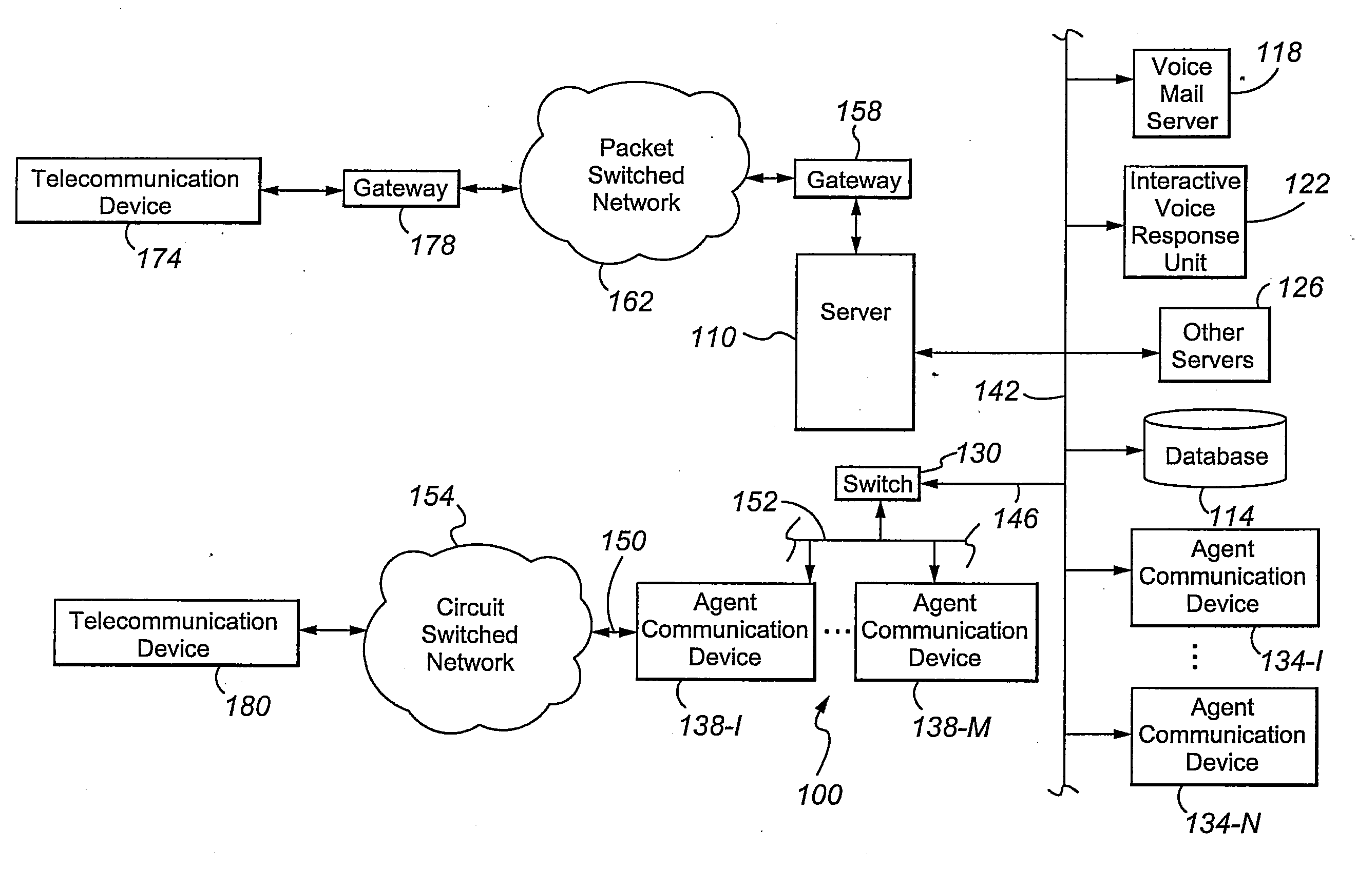
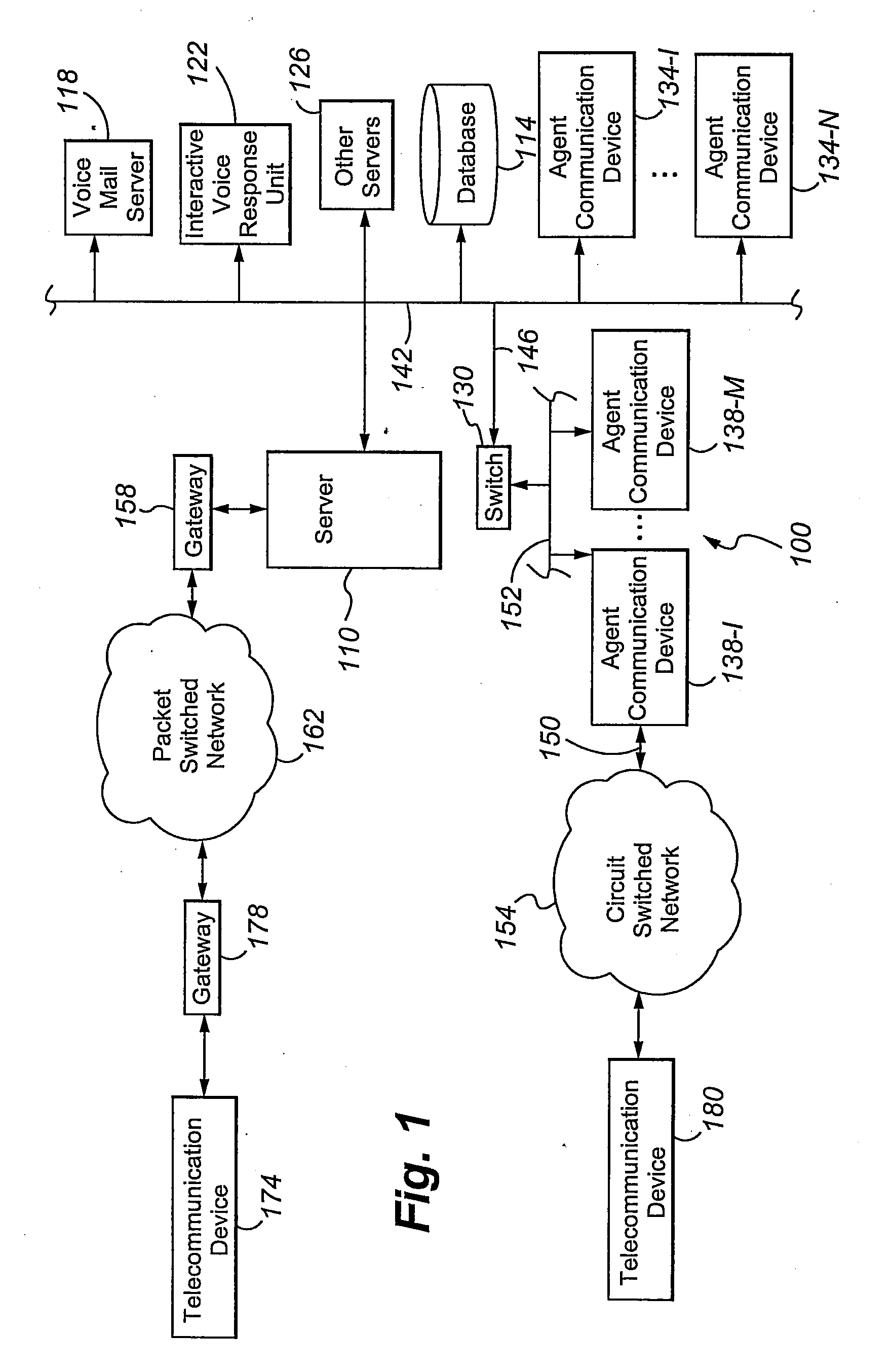
[0028]FIG. 1 shows an illustrative embodiment of the present invention. A contact center 100 comprises a central server 110, a set of data stores or databases 114 containing contact or customer related information and other information that can enhance the value and efficiency of the contact processing, and a plurality of servers, namely a voice mail server 118, an Interactive Voice Response unit or IVR 122, and other servers 126 (such as a predictive dialer), a...


PUM


Abstract

An event reporting system includes a computational component 228 operable (a) to receive notification of a change to an attribute of an entity, the entity, prior to the change, being associated with a first surrogate key, and (b) to defer the use of a second surrogate key for the entity until a selected time. The second surrogate key was generated to reflect the change.

Description

FIELD OF THE INVENTION[0001]The present invention is directed generally to event processing and specifically to monitoring agent performance.BACKGROUND OF THE INVENTION[0002]Contact centers, such as Automatic Call Distribution or ACD systems, are employed by many enterprises to service customer contacts. A typical contact center includes a switch and / or server to receive and route incoming packet-switched and / or circuit-switched contacts and one or more resources, such as human agents and automated resources (e.g., Interactive Voice Response (IVR) units), to service the incoming contacts. Contact centers distribute contacts, whether inbound or outbound, for servicing to any suitable resource according to predefined criteria. In many existing systems, the criteria for servicing the contact from the moment that the contact center becomes aware of the contact until the contact is connected to an agent are customer-specifiable (i.e., programmable by the operator of the contact center), ...

Claims


Application Information

Patent Timeline
Patent Type & Authority Applications(United States)
IPC IPC(8): G06F17/30
CPCG06F17/30592G06F16/283
Inventor BLAND, MICHAEL ALANFRIEDL, STEPHAN EDWARDJENNINGS, TERRY DONOLSON, JEFFREY JAMESYOUNGKIN, RICHARD SHAFFER
Owner AVAYA INC
Why Eureka
Try Eureka