This helps you quickly interpret patents by identifying the three key elements:
Problems solved by technology
Method used
Benefits of technology
Benefits of technology
[0012]The present invention relates to a shoe sole and a shoe incorporating the shoe sole that can be tuned to offset a wearer's side-to-side balance and thereby encourage a wearer's conditioning and toning. The present inventions further relates to a shoe sole and a shoe with additional structures that can be used to additionally affect a wearer's balance and to tune stability, energy return and cushioning.
[0025]In one aspect, the concavely curved leaf springs are arranged in an alternating pattern with the convexly curved leaf springs. In another aspect, the midsole also includes an upper midsole layer and a lower midsole layer. The upper midsole layer includes recesses in its lower surface for receiving the concavely curved leaf springs and the lower midsole layer includes recesses in its upper surface for receiving the convexly curved leaf springs. In this way, the lower midsole layer can form a gasket to fill the spaces between the lower midsole surface and the leaf springs.
Problems solved by technology
While athletic shoes are usually designed with stability in mind, some prior art shoes are intentionally designed to promote a lengthwise instability.
The moving air creates a natural instability and forces your muscles to adapt to the air volume within the pods.
Method used
Image
Click on the blue label to locate the original text in one second.
Reading with bidirectional positioning of images and text.
Examples
embodiment 162
[0098]Because of the discrete nature of the concavely curved leaf springs 144 and convexly curved leaf springs 150, different areas of the shoe sole 10, for example (forefoot, rearfoot, midfoot), on different sides (medial and lateral) of the shoe sole 10 can be independently stiffened or softened to create any desired balance of cushioning, energy return, and stability. FIG. 9 shows an embodiment 162 of the structure that includes a central portion 164 in which the opposing concavely curved leaf springs 166 and convexly curved leaf springs 168 are of two different stiffnesses. The different stiffnesses may be provided by using different materials, different densities of a material, different thicknesses of a material, and so on. For example, the concavely curved leaf springs 166 may be made softer to provide additional cushioning and the convexly curved leaf springs 168 may be made harder to provide additional rebound. Additionally, the stiffness of the convexly curved leaf springs...
embodiment 170
[0099]Additionally, the length of the structure may be tuned to direct support from the leaf springs to various areas of the shoe sole. For example, FIG. 10A shows an embodiment 170 of the structure that includes a series of concavely 172 and convexly curved leaf springs 174 which extends from a heel to three-quarters the length of the shoe sole. Another embodiment, shown in FIG. 10B, includes a structure 176 that is adapted to extend from a rearfoot portion to a forefoot portion of a shoe sole of the present invention. In one embodiment, show in FIG. 10C, a structure 178 includes a series of concavely 180 and convexly 182 curved leaf springs adapted to extend from a heel to three-quarters the length of a shoe sole. The structure of FIG. 10C further includes upper 184 and lower extensions 186 that extend forward of the leaf springs 180, 182 into the forefoot portion of a shoe sole.
[0100]In another embodiment of the present invention, as shown in FIG. 11, a U-shaped structure 188 may...
embodiment 10
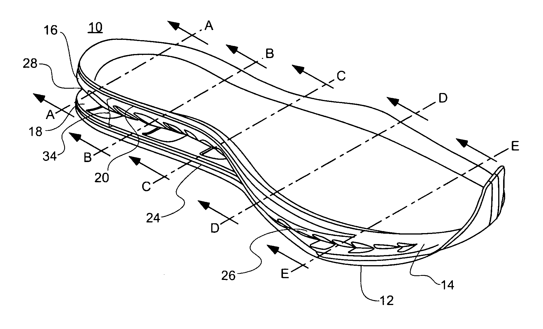
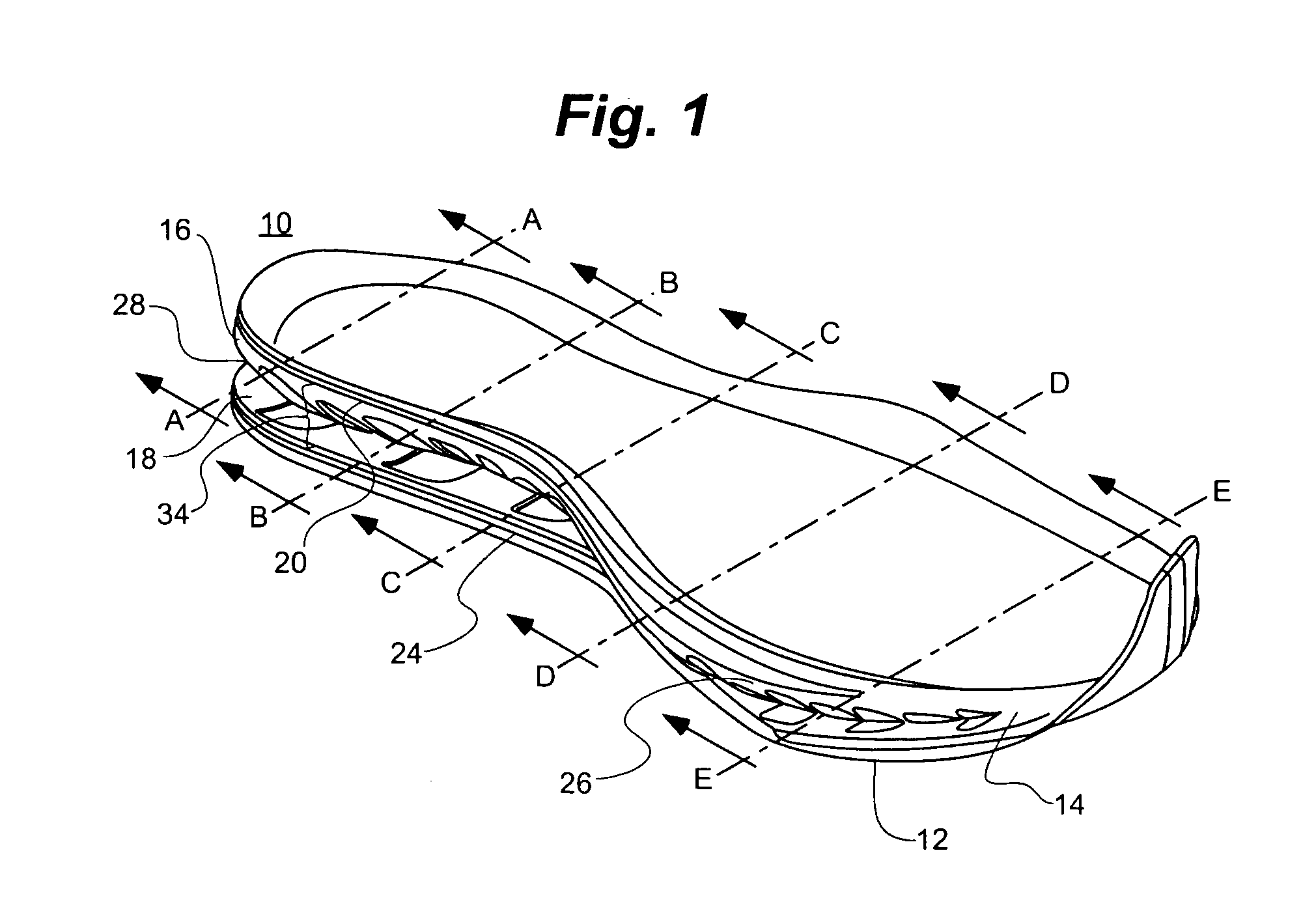
[0104]An embodiment of an outsole 208 with a curvature about a longitudinal axis 210 can be seen in FIGS. 13A, 13B, 13C, 13D and 13E, and FIGS. 14A, 14B, 14C, 14D and 14E, which show cross sections of the embodiment 10 of a shoe sole of FIG. 1 at lines A-A, B-B, C-C, D-D, and E-E, respectively. In this embodiment, the contact point 212 in the rearfoot portion of the outsole 208 is toward the medial side of the shoe sole 10, as shown in FIGS. 13A and 14A. The contact point 212 is shifted more towards the center of the shoe sole 10 in the cross section showing points further forward in the in shoe sole 10 in FIGS. 13B and 14B and 13C and 14C. The contact point 212 may be shifted towards the lateral side of the shoe sole 10 in the forefoot portion of the shoe sole 10 as shown in FIGS. 13D and 14D. In one embodiment, the curvature of the outsole 208 may shift toward the extreme lateral side of the shoe sole 10 in the toe area of the shoe sole 10, as shown in FIGS. 13E and 14E.
[0105]Addi...
PUM
Abstract
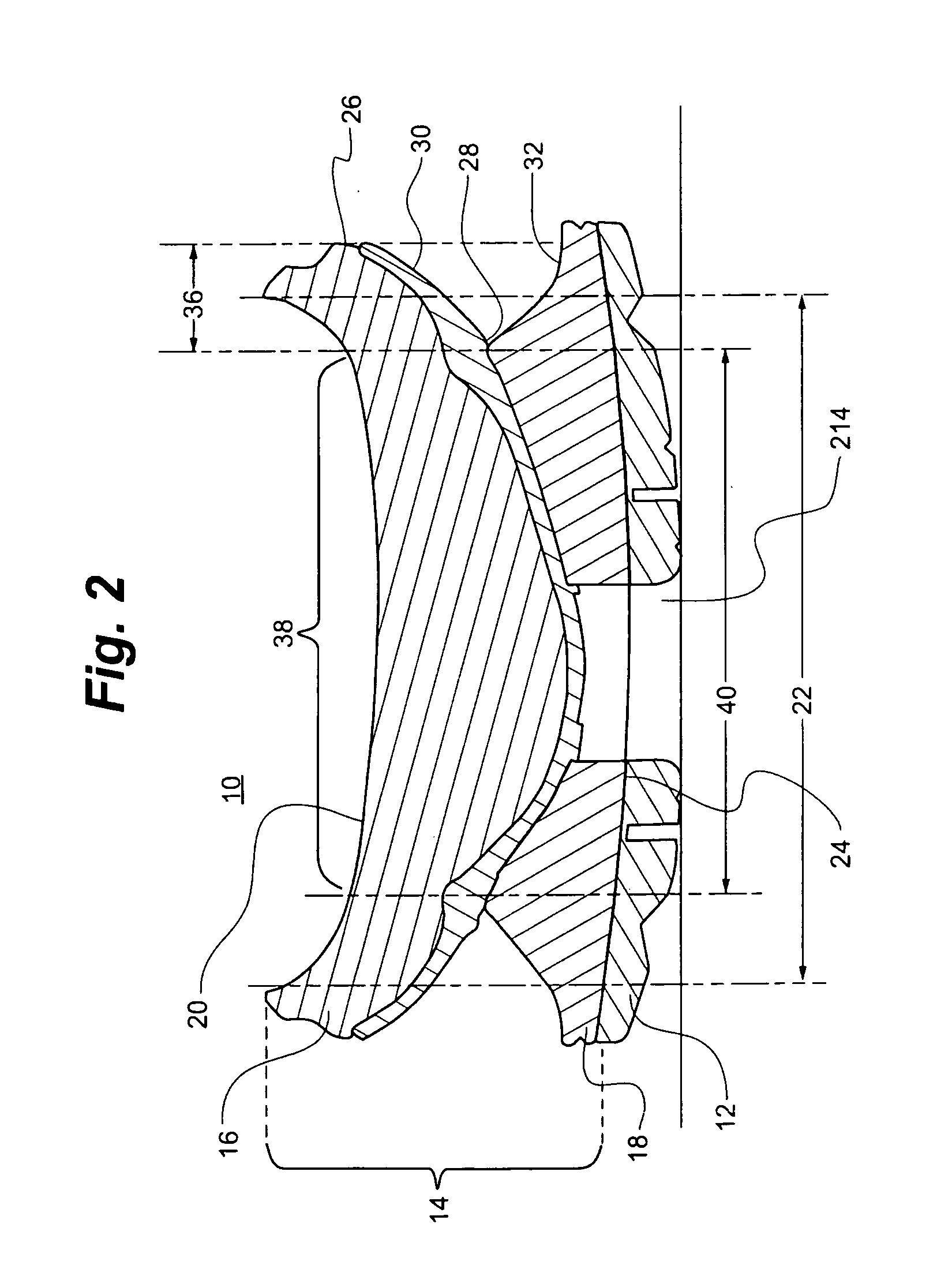
A shoe sole and shoe are provided for offsetting a wearer's side-to-side balance to encourage a wearer's conditioning and toning. The shoe sole includes a midsole width that underlies and supports a wearer's foot, and an upper midsole portion undercut at its peripheral sidewall around the heel to define a horizontal indentation. A lower midsole portion has a corresponding “undercut” in its upper surface that angles downward and outward from the indentation. The depth of the indentation forms a balancing portion between the medially and laterally placed indentations that is narrower than the midsole width, thereby forcing the wearer to adjust one's walking gait to maintain balance over the balancing portion. A structure with a base portion can be disposed along the indentation with upward and or downward extending extensions disposed along the peripheral sidewall. The structure can include leaf springs extending transversely over a central midsole portion.
Description
CROSS-REFERENCE TO RELATED APPLICATIONS[0001]This application claims priority to U.S. Provisional Application Ser. No. 61 / 210,871, filed Mar. 23, 2009, the entirety of which is incorporated herein by reference thereto.TECHNICAL FIELD[0002]The present invention relates to a shoe sole and a shoe incorporating the shoe sole and, in particular, to a shoe sole including a horizontal indentation in a peripheral sidewall of the shoe sole and preferably additional structure that can be tuned to offset a wearer's side-to-side balance and thereby encourage a wearer's conditioning and toning.BACKGROUND OF THE INVENTION[0003]Modern athletic footwear typically include an outsole, midsole, and insole. The midsole is positioned between the ground-contacting outsole and the insole and typically includes one or more foams for attenuating impact forces generated upon the contact of a wearer's shoe on the ground. Foams such as ethelene vinyl acetate (EVA) also have resilience for energy return and are...
Claims
Application Information
Patent Timeline
Application Date:The date an application was filed.
Publication Date:The date a patent or application was officially published.
First Publication Date:The earliest publication date of a patent with the same application number.
Issue Date:Publication date of the patent grant document.
PCT Entry Date:The Entry date of PCT National Phase.
Estimated Expiry Date:The statutory expiry date of a patent right according to the Patent Law, and it is the longest term of protection that the patent right can achieve without the termination of the patent right due to other reasons(Term extension factor has been taken into account ).
Invalid Date:Actual expiry date is based on effective date or publication date of legal transaction data of invalid patent.

